Download
1 / 48
480 likes | 484 Views
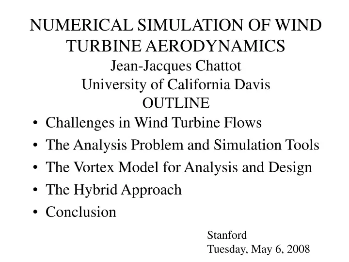
NUMERICAL SIMULATION OF WIND TURBINE AERODYNAMICS Jean-Jacques Chattot University of California Davis OUTLINE. Challenges in Wind Turbine Flows The Analysis Problem and Simulation Tools The Vortex Model for Analysis and Design The Hybrid Approach Conclusion. Stanford Tuesday, May 6, 2008.

E N D
NUMERICAL SIMULATION OF WIND TURBINE AERODYNAMICSJean-Jacques ChattotUniversity of California DavisOUTLINE • Challenges in Wind Turbine Flows • The Analysis Problem and Simulation Tools • The Vortex Model for Analysis and Design • The Hybrid Approach • Conclusion Stanford Tuesday, May 6, 2008
CHALLENGES IN WIND TURBINE FLOW ANALYSIS AND DESIGN • Vortex Structure - importance of maintaining vortex structure 10-20 R - free wake vs. prescribed wake models - nonlinear effects on swept tips and winglets • High Incidence on Blades - separated flows and 3-D viscous effects • Unsteady Effects - yaw, tower interaction, earth boundary layer • Blade Flexibility
THE ANALYSIS PROBLEM AND SIMULATION TOOLS • Actuator Disk Theory (1-D Flow) • Empirical Dynamic Models (Aeroelasticity) • Vortex Models - prescribed wake + equilibrium condition - free wake - applied to design of blades for maximum power at given thrust on tower (including sweep and winglets) • Euler/Navier-Stokes Codes - 10 M grid points, still dissipates wake - not practical for design
THE VORTEX MODEL FOR ANALYSIS AND DESIGN • Goldstein Model • Simplified Treatment of Wake • Rigid Wake Model • “Ultimate Wake” Equilibrium Condition • Base Helix Geometry Used for Steady and Unsteady Flows • Application of Biot-Savart Law • Blade Element Flow Conditions • 2-D Viscous Polar
GOLDSTEIN MODEL Vortex sheet constructed as perfect helix with variable pitch
SIMPLIFIED TREATMENT OF WAKE • No stream tube expansion, no sheet edge roll-up (second-order effects) • Vortex sheet constructed as perfect helix called the “base helix” corresponding to zero yaw
“ULTIMATE WAKE” EQUILIBRIUM CONDITION Induced axial velocity from average power (iterations):
VWind = 7m/s INFLUENCE OF WAKE ON RESULTS
BASE HELIX GEOMETRY USED FOR STEADY AND UNSTEADY FLOWS Vorticity is convected along the base helix, not the displaced helix, a first-order approximation
ANALYSIS RESULTS: STEADY FLOW Power output comparison
YAWED FLOW Time-averaged power versus velocity at different yaw angles =10 deg =5 deg =20 deg =30 deg
TOWER INTERFERENCE MODEL • Simplified Model • NREL Root Flap Bending Moment Comparison • - Effect of Incoming Velocity V=5, 8 and 10 m/s • - Effect of Yaw yaw=5, 10 and 20 deg
DESIGN METHODOLOGY • Minimize Torque Coefficient Thrust Coefficient is Lagrange multiplier
DESIGN METHODOLOGY • Given “adv” – Given profile (2-D viscous polar) or corresponding to • Optimum circulation • Design:
Vortex Line Method (VLM) – Operating Points DESIGN AND ANALYSIS OF A ROTOR BLADE DESIGN TEST CASE
HYBRID APPROACH • Use Best Capabilities of Physical Models • - Navier-Stokes for near-field viscous flow • - Vortex model for far-field inviscid wake • Couple Navier-Stokes with Vortex Model • - improved efficiency • - improved accuracy
HYBRID METHODOLOGY Navier-Stokes Biot-Savart Law (discrete) Boundary of Navier-Stokes Zone Vortex Method Bound Vortex Converged for … Vortex Filament Coupling Methodology
PCS/VLM COMPARISON Optimum Blade designed with VLM VLM PCS Thrust [N] 509.62 508.31 Tangential Force [N] -183.63 -179.89 Bending Moment [Nm] 1803.1 1814.8 Torque [Nm] -588.82 -583.80 Power [kW] 8.879 8.804 Difference in Power : 0.84 %
RESULTS: STEADY FLOWNREL ROTOR Power output comparison
PCS k-ω : Γj PCS k-ω : cl VLM : Γj VLM : cl PCS/VLM COMPARISON
Trailing Vorticity is traceable with the spanwise velocity component at 5%-10% chord length downstream of the blade’s trailing edge. These complex 3D effects are very difficult to detect with ‘strip theory’. The PCS solver on the other hand is capable of disclosing such phenomena close to Peak Power. VWind = 7m/s VWind = 9m/s VWind = 10m/s VWind = 11m/s TRAILING VORTICITY NEAR PEAK POWER
CONCLUSIONS • Vortex Model: simple, efficient, can be used for design • Stand-alone Navier-Stokes: too expensive, dissipates wake, cannot be used for design • Hybrid Model: takes best of both models to create most efficient and reliable simulation tool • Next Frontier: aeroelasticity and multidisciplinary design
RECENT PUBLICATIONS • S. H. Schmitz, J.-J. Chattot, “A coupled Navier-Stokes/Vortex-Panel solver for the numerical analysis of wind turbines”, Computers and Fluids, Special Issue, 35: 742-745 (2006). • S. H. Schmitz, J.-J. Chattot, “A parallelized coupled Navier-Stokes/Vortex-Panel solver”, Journal of Solar Energy Engineering, 127:475-487 (2005). • J.-J. Chattot, “Extension of a helicoidal vortex model to account for blade flexibility and tower interference”, Journal of Solar Energy Engineering, 128:455-460 (2006). • S. H. Schmitz, J.-J. Chattot, “Characterization of three-dimensional effects for the rotating and parked NREL phase VI wind turbine”, Journal of Solar Energy Engineering, 128:445-454 (2006). • J.-J. Chattot, “Helicoidal vortex model for wind turbine aeroelastic simulation”, Computers and Structures, 85:1072-1079 (2007). • S. H. Schmitz, J.-J. Chattot, “A method for aerodynamic analysis of wind turbines at peak power”, Journal of Propulsion and Power, 23(1):243-246 (2007). • J.-J. Chattot, “Effects of blade tip modifications on wind turbine performance using vortex model”, AIAA 2008-1315 (2008).