Download
1 / 62
630 likes | 885 Views
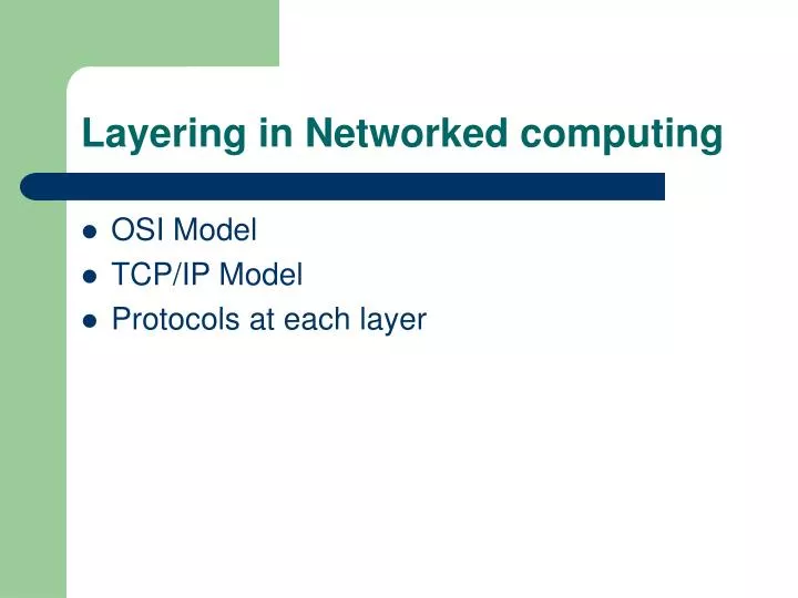
Layering in Networked computing. OSI Model TCP/IP Model Protocols at each layer. Learning outcomes. Understand the need of layering in Networked computing Understand the OSI model and the tcp/ip model Understand the function protocols and their role at each layer. TCP protocol

E N D
Layering in Networked computing • OSI Model • TCP/IP Model • Protocols at each layer
Learning outcomes • Understand the need of layering in Networked computing • Understand the OSI model and the tcp/ip model • Understand the function protocols and their role at each layer. • TCP protocol • UDP protocol • Understand the role of header in communication between layers • Understand how data sent from one host arrive to the target host.
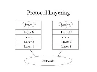
What is layering in Networked computing? • Breaks down communication into smaller, simpler parts.
Why a layered model? • Easier to teach communication process. • Speeds development, changes in one layer does not affect how the other levels works. • Standardization across manufactures. • Allows different hardware and software to work together. • Reduces complexity
The OSI Model • OSI “ Open Systems Interconnection". • OSI model was first introduced in 1984 by the International Organization for Standardization (ISO). • Outlines WHAT needs to be done to send data from one computer to another. • Not HOW it should be done. • Protocols stacks handle how data is prepared for transmittal (to be transmitted) • In the OSI model, The specification needed • are contained in 7 different layers that interact with each other.
What is “THE MODEL?” • Commonly referred to as the OSI reference model. • The OSI model • is a theoretical blueprint that helps us understand how data gets from one user’s computer to another. • It is also a model that helps develop standards so that all of our hardware and software talks nicely to each other. • It aids standardization of networking technologies by providing an organized structure for hardware and software developers to follow, to insure there products are compatible with current and future technologies.
7 Layer OSI Model • Why use a reference model? • Serves as an outline of rules for how protocols can be used to allow communication between computers. • Each layer has its own function and provides support to other layers. • Other reference models are in use. • Most well known is the TCP/IP reference model. • We will compare OSI and TCP/IP models • As computing requirements increased, the network modeling had to evolve to meet ever increasing demands of larger networks and multiple venders. • Problems and technology advances also added to the demands for changes in network modeling.
Hardware & Software Hardware & Software Evolution of the 7-Layers • Single Layer Model - First Communication Between Computer Devices • Dedicated copper wire or radio link • Hardware & software inextricably intertwined • Single specification for all aspects of communication 1 DEVICE A DEVICE B www.howtheosimodelworks.com
Application Application Technical Standards Technical Standards Evolution of the 7-Layers (1) • Two Layer Model • Problem: Applications were being developed to run over ever-increasing number of media/signaling systems. • Solution: Separate application aspects from technical (signaling and routing) aspects • Application Layer: Concerned with user interface, file access and file transfer 1 www.howtheosimodelworks.com
Application Application Network Network Data-Link Data-Link Physical Physical Evolution of the 7-Layers (3) • Four Layer Model - Network connectivity inherently requires travel over intermediate devices (nodes) • Technical Standards Level divided into Network, Data-link and Physical Layers 1 http://www.howtheosimodelworks.com/
Evolution of the 7-Layers (3) cont. • Physical Layer • Describes physical aspects of network: cards, wires, etc • Specifies interconnect topologies and devices • Network Layer • Defines a standard method for operating between nodes • Address scheme is defined (IP) • Accounts for varying topologies • Data-Link • Works with Network Layer to translate logical addresses (IP) into hardware addresses (MAC) for transmission • Defines a single link protocol for transfer between two nodes
Application Application Transport Transport Network Network Data-Link Data-Link Physical Physical Evolution of the 7-Layers (4) • Five Layer Model – Increase Quality of Service (QOS) • Variable levels of data integrity in network • Additional data exchanges to ensure connectivity over worst conditions • Became the Transport Layer 1 http://www.howtheosimodelworks.com
Application Application Session Session Transport Transport Network Network Data-Link Data-Link Physical Physical Evolution of the 7-Layers (5) • Six Layer Model - Dialogue Control and Dialogue Separation • Means of synchronizing transfer of data packets • Allows for checkpointing to see if data arrives (at nodes and end stations) • Became Session Layer 1 http://www.howtheosimodelworks.com/
Application Application Presentation Presentation Session Session Transport Transport Network Network Data-Link Data-Link Physical Physical Evolution of the 7-Layers (6) • The Seven Layer OSI Model - Addition of Management and Security • Standardizing notation or syntax for application messages (abstract syntax) • Set of encoding rules (transfer syntax) • Became the Presentation Layer 1 http://www.howtheosimodelworks.com/
Gives end-user applications access to network resources • Where is it on my computer? • Workstation or Server Service in MS Windows 3
Session Layer • Allows applications to maintain an ongoing session • Where is it on my computer? • Workstation and Server Service (MS) • Windows Client for NetWare (NetWare) 3
Transport Layer • Provides reliable data delivery • It’s the TCP in TCP/IP • Receives info from upper layers and segments it into packets • Can provide error detection and correction 3
Figure 2.9Transport layer The transport layer is responsible for the delivery of a message from one process to another.
Network Layer • Provides network-wide addressing and a mechanism to move packets between networks (routing) • Responsibilities: • Network addressing • Routing • Example: • IP from TCP/IP 3
Network layer The network layer is responsible for the delivery of individual packets from the source host to the destination host.
Network Addresses • Network-wide addresses • Used to transfer data across subnets • Used by routers for packet forwarding • Example: • IP Address • Where is it on my computer? • TCP/IP Software
Data Link Layer • Places data and retrieves it from the physical layer and provides error detection capabilities 3
Data link layer The data link layer is responsible for moving frames from one hop (node) to the next.
Sub-layers of the Data Link Layer • MAC (Media Access Control) • Gives data to the NIC • Controls access to the media through: • CSMA/CD Carrier Sense Multiple Access/Collision Detection • Token passing • LLC (Logical Link Layer) • Manages the data link interface (or Service Access Points (SAPs)) • Can detect some transmission errors using a Cyclic Redundancy Check (CRC). If the packet is bad the LLC will request the sender to resend that particular packet.
Physical Layer • Determines the specs for all physical components • Cabling • Interconnect methods (topology / devices) • Data encoding (bits to waves) • Electrical properties • Examples: • Ethernet (IEEE 802.3) • Token Ring (IEEE 802.5) • Wireless (IEEE 802.11b) 3
Physical layer The physical layer is responsiblefor the movement of individual bits from one hop (node) to the next.
Physical Layer (cont’d) • What are the Physical Layer components on my computer? • NIC • Network Interface Card • Has a unique 12 character Hexadecimal number permanently burned into it at the manufacturer. • The number is the MAC Address/Physical address of a computer • Cabling • Twister Pair • Fiber Optic • Coax Cable
Each layer contains a Protocol Data Unit (PDU) PDU’s are used for peer-to-peer contact between corresponding layers. Data is handled by the top three layers, then Segmented by the Transport layer. The Network layer places it into packets and the Data Link frames the packets for transmission. Physical layer converts it to bits and sends it out over the media. The receiving computer reverses the process using the information contained in the PDU. How Does It All Work Together 2
Data Encapsulation In TCP/IP • At each layer in the TCP/IP protocol stack • Outgoing data is packaged and identified for delivery to the layer underneath • PDU – Packet Data Unit – the “envelop” information attached to a packet at a particular TCP/IP protocol • e.g. header and trailer • Header • PDU’s own particular opening component • Identifies the protocol in use, the sender and intended recipient • Trailer (or packet trailer) • Provides data integrity checks for the payload
A- Write a 20 page letter to a foreign country. P- Translate the letter so the receiver can read it. S- Insure the intended recipient can receive letter. T- Separate and number pages. Like registered mail, tracks delivery and requests another package if one is “lost” or “damaged” in the mail. N- Postal Center sorting letters by zip code to route them closer to destination. D- Local Post Office determining which vehicles to deliver letters. P- Physical Trucks, Planes, Rail, autos, etc which carry letter between stations. Application Presentation Session Transport Network Data-Link Physical The Postal Analogy How would the OSI compare to the regular Post Office
7 - Application All 6 - Presentation People 5 - Session Seem 4 - Transport To 3 - Network Need 2 - Data Link Data 1 - Physical Processing Remembering the 7 Layers
TCP/IP model development • The late-60s The Defense Advance Research Projects Agency (DARPA) originally developed Transmission Control Protocol/Internet Protocol (TCP/IP) to interconnect various defense department computer networks. • The Internet, an International Wide Area Network, uses TCP/IP to connect networks across the world.
4 layers of the TCP/IP model • Layer 4:Application • Layer 3:Transport • Layer 2:Internet • Layer 1:Network access It is important to note that some of the layers in the TCP/IP model have the same name as layers in the OSI model. Do not confuse the layers of the two models.
The network access layer • Concerned with all of the issues that an IP packet requires to actually make the physical link. All the details in the OSI physical and data link layers. • Electrical, mechanical, procedural and functional specifications. • Data rate, Distances, Physical connector. • Frames, physical addressing. • Synchronization, flow control, error control.
The internet layer • Send source packets from any network on the internetwork and have them arrive at the destination independent of the path and networks they took to get there. • Packets, Logical addressing. • Internet Protocol (IP). • Route , routing table, routing protocol.
The transport layer • The transport layer deals with the quality-of-service issues of reliability, flow control, and error correction. • Segments, data stream, datagram. • Connection oriented and connectionless. • Transmission control protocol (TCP). • User datagram protocol (UDP). • End-to-end flow control. • Error detection and recovery.
TCP/IP Reference Model (cont) • 3. Transport layer (layer 3) • Allows end-to-end communication • Connection establishment, error control, flow control • Two main protocols at this level • Transmission control protocol (TCP), • Connection oriented • Connection established before sending data • Reliable • user datagram protocol (UDP) • Connectionless • Sending data without establishing connection • Fast but unreliable
The application layer • Handles high-level protocols, issues of representation, encoding, and dialog control. • The TCP/IP combines all application-related issues into one layer, and assures this data is properly packaged for the next layer. • FTP, HTTP, SMNP, DNS ... • Format of data, data structure, encode … • Dialog control, session management …
TCP/IP Reference Model Layer Protocols Application HTTP TELNET FTP SMTP SNMP Transport TCP UDP Internet IP ICMP Network Access(Host-to-network) ETHERNET PACKET RADIO
Protocols at the application layer • HTTP: • browser and web server communicatin • FTP : • file transfer protocol • TELNET: • remote login protocol • POP3: Retrieve email • POP3 is designed to delete mail on the server as soon as the user has downloaded it • IMAP (Internet Message Access Protocol ) • Retrieve emails, • retaining e-mail on the server and for organizing it in folders on the serve
Protocols at the transport layer • Transmission control protocol (TCP), • Connection oriented • Connection established before sending data • Reliable • user datagram protocol (UDP) • Connectionless • Sending data without establishing connection • Fast but unreliable