Download
1 / 23
240 likes | 394 Views
Central Control Unit. Extension Power Supply. Audio Expander. Central Control Equipment for DCN Next Generation. 2. 1. 3. 4. Central Control Unit. 1 Mains on/off switch A switch to switch on and off the CCU.

E N D
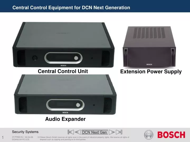
Central Control Unit Extension Power Supply Audio Expander Central Control Equipment for DCN Next Generation DCNNG SA PO CCE
2 1 3 4 Central Control Unit • 1Mains on/off switch A switch to switch on and off the CCU. • 2Menu display A 2x16 character LCD display gives information about the CCU. It is also used to configure the system. • 3Menu button A turn-and-push button to operate the menu in combination with the display. • 4Monitoring headphones output A 3.5 mm jack socket to connect headphones for audio monitoring purposes. I&U Instructions DCNNG SA PO CCE
6 7 5 10 11 12 14 8 9 12 11 13 Central Control Unit • 5RS232 ports 2 x 9-pin Sub-D connector for: • Open interface (for remote control functions) • Terminal (service diagnostics) • Full protocol (direct PC control) • Camera Control • 6Mains inlet A socket to connect the CCU to the mains. • 7Ground A connection to mechanically ground the CCU. I&U Instructions DCNNG SA PO CCE
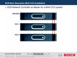
10 11 12 14 8 9 12 11 13 Central Control Unit • 8Optical network Two sockets to connect the CCU to the optical network for connecting other optical devices to the system. Each socket has a red LED that indicates overload situations. Note: Even if only one of the optical network sockets has a power overload, both overload LEDs will be activated and the power will be removed from both sockets. • 9DCN sockets Two sockets to connect the DCN Next Generation units to the CCU. Each socket can supply 65 Watt and has a red LED that indicates overload situations. • 10Fault contact A potential-free change-over relay contact that indicates the correct operation of the CCU. I&U Instructions DCNNG SA PO CCE
10 11 12 14 8 9 12 11 13 • 11Audio input Two audio inputs to insert analogue audio signals that originate from external audio sources into the system.` • 12 Audio output Two audio outputs to extract analogue audio signals from the system. Central Control Unit I&U Instructions DCNNG SA PO CCE
Central Control Unit 10 11 12 14 8 9 12 11 13 • 13Voltage selector to select the local mains voltage 115/230. • 14Fuse holder with a fuse that protects the power supply of the CCU. I&U Instructions DCNNG SA PO CCE
Basic Central Control Unit • 5RS232 ports 1 x 9-pin Sub-D connector for: • Camera Control or • Open interface (for remote control functions) or • Terminal (service diagnostics) or • Full protocol (direct PC control) 5 9 10 12 8 10 9 11 I&U Instructions DCNNG SA PO CCE
9Audio input Two unbalanced audio inputs to insert analogue audio signals from external audio sources into the system. • 10 Audio output Two audio outputs to extract analogue audio signals from the system. Basic Central Control Unit 9 10 12 8 10 9 11 I&U Instructions DCNNG SA PO CCE
PCB Central Control Unit total view 18 17 16 15 19 20 21 22 23 I&U Instructions DCNNG SA PO CCE
18 17 16 15 PCB Central Control Unit • 15Software indicators ThreeLEDs: • Yellow the software is running • Green the software is running. • Red LED lights up during system reset or low voltage. • 17X605 Jumper To specify whether the watchdog function is set. • 18Reset button To reset the CCU. I&U Instructions DCNNG SA PO CCE
PCB Central Control Unit 181716 15 • 16S600 Dip switches to configure the DCN. I&U Instructions DCNNG SA PO CCE
PCB Central Control Unit • 19Optical network processor indicator A LED that indicates that media processor is running. • 21X600 Jumper to specify whether a backup battery is connected. The back-up battery is used to hold the settings when the power is switched off. • 22 X104 Jumper to connect the mechanical ground to the electrical ground. By default, the jumper is placed free of mechanical ground on positions 2 and 3. • 23Fuse to protect the main PCB of the CCU when the wrong voltage has been selected using the voltage selector on the rear. 19 20 21 22 23 I&U Instructions DCNNG SA PO CCE
PCB Central Control Unit • 20S500 Dip switches to configure the RS232 ports. I&U Instructions DCNNG SA PO CCE
1 Extension Power Supply • 1Power indicator Thegreen LED that indicates that the power supply is on. When connected to the system, it is automatically activated on at the moment the CCU is switched on. I&U Instructions DCNNG SA PO CCE
2 3 4 5 6 Extension Power Supply • 2DCN cable with a male, 6-pole, circular connectorto connect the extension power supply to the system. • 3DCN socket A female, 6-pole, circular socket to loop-through the(trunk) extension power supply in the system. The socket can supply85 Watt and has a red LED to indicate overload situations. • 4DCN sockets Two female, 6-pole, circular sockets to create tap-offs in(tap-off’s) the system. Each socket can supply 85 Watt and has a red LED to indicate overload situations. I&U Instructions DCNNG SA PO CCE
2 3 4 5 6 Extension Power Supply • 5Mains inlet to connect the extension power supply to the mains. • 6Fuse holder with a fuse to protect the extension power supply.T5A 125 V (100 - 120 V (AC)) T4A H 230 V (220 - 240 V(AC)) I&U Instructions DCNNG SA PO CCE
3 2 1 Audio Expander Analogue and Digital • Remote controlled by the Central Control Unit • 1Menu display A 2x16 character LCD display gives information about the audio expander analogue. It is also used as an interactive display for configuring the audio expander. • 2Menu button A turn-and-push button to operate the menu in combination with the display. • 3Monitoring headphones output A 3.5 mm jack socket to connect headphones for audio monitoring purposes. I&U Instructions DCNNG SA PO CCE
4 5 5 6 7 6 5 6 8 9 6 5 Audio Expander Analogue • 4Control inputs Eight control inputs to enable and disable the 4 audio inputs and 4 audio outputs of the audio expander. • 5 Audio inputs Four audio inputs to insert analogue audio signals that originate from external audio sources.Maximum input signal level : 18 dBV (XLR), 6 dBV (cinch) Nominal level range : -12 to 0 dB with respect to max. input level. • 6Audio outputs Four audio outputs to extract analogue audio signals.Maximum Output signal level : 18 dBV (XLR), 6 dBV (cinch) Nominal level range : -30 to 0 dB with respect to max. output level. I&U Instructions DCNNG SA PO CCE
4 5 5 6 7 6 5 6 8 9 6 5 Audio Expander Analogue • 7GroundA connection to mechanically ground the audio expander (when mounted in a rack). • 8Optical network Two optical network sockets to connect the audio expander to the optical network. • 9Control outputs Five control outputs to indicate if audio outputs and the optical network connection are active. I&U Instructions DCNNG SA PO CCE
Network processor Mem P Control outputs Control inputs Digital In Digital Out Audio inputs Audio outputs DSP D/A A/D Display M I²C POF transducers D/A Network redundancy switching System Bus PS DC/DC Audio Expander Analogue • Block diagram DCNNG SA PO CCE
4 5 8 9 6 7 9 8 Audio Expander Digital • 4Control inputs Eight control inputs to enable and disable the 4 audio inputs and 4 audio outputs of the audio expander. • 5 GroundA connection to mechanically ground the audio expander (when mounted in a rack). • 6Optical network Two optical network sockets to connect the audio expander to the optical network. • 7Control outputs Five control outputs to indicate if audio outputs and the optical network connection are active I&U Instructions DCNNG SA PO CCE
Audio Expander Digital 4 5 • 8 Audio inputs from external digital audio sources 1 XLR socket with transformer for AES/EBU signals. 1cinch socket for SPDIF signals. • 9Audio outputsto external digital audio devices 1 XLR socket with transformer for AES/EBU signals. 1cinch socket for SPDIF signals. • Notes: • When the interlock mode in Interpretation system is “None”, the audio inputs of the digital audio expander are disabled • Each audio input and output can contain a maximum of 2 channels (L and R). • The digital audio expander does not change stereo in mono signals. 8 9 6 7 9 8 I&U Instructions DCNNG SA PO CCE
Central Control Equipment End of section SA PO Menu DCNNG SA PO CCE