Download
1 / 12
120 likes | 258 Views
Detector Technologies for an All-Semiconductor Tracker at the sLHC Hartmut F.W. Sadrozinski SCIPP, UC Santa Cruz. Divide the sLHC Tracker into 3 radial regions with 10x fluence increase Fluence is a factor 10 higher than at the same radius in LHC:

E N D
Detector Technologies for an All-Semiconductor Tracker at the sLHC Hartmut F.W. Sadrozinski SCIPP, UC Santa Cruz
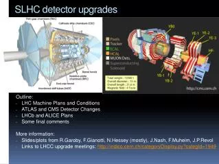
Divide the sLHC Tracker into 3 radial regions with 10x fluence increase Fluence is a factor 10 higher than at the same radius in LHC: “ move systems outward” SCT -> Straw tubes, Pixels -> SCT, need new Pixels System performance can then be estimated. Guess at a specification of the charge needed in the 3 regions:
Required Studies Tracking detector technologies are limited by radiation The limiting process is different in the different radial regions This motivates different studies
Simple SSD layout at Radius > 20 cm 3 cm strip length vs. 12 for SCT R > 50 cm: Single layers, sz 1cm 20 < R < 50 cm: Back-to-back single-sided sz 1mm Problem: Confusion of stereo assignment Mitigated by length reduction But strips are much easier to build Explore availability of p-type substrates No type inversion Collect electrons Partial depletion operation Potential for semi-3D?
SSD technology for radius > 20 cm: Recent results from ATLAS SCT beam test illustrates problem with charge collection after type inversion in common p-on-n detectors. N-on-p would provide much more “head room” in bias voltage (cheaper than n-in-n ?) But: electrons have larger Lorenz angle (tilt of SSD)
Technologies for Inner-most “Pixels” System • Limitation: Trapping • 1. Charge Trapping in Si SSD: • Collected Charge Q = Qo*e(depletion)* e(trapping) • e(depletion) depends on Vbias , Vdep -> effective detector thickness w • e(trapping) = exp(-tc/ tt), • tc : Collection time tt : Trapping time • Trapping time is reduced with radiation damage: • 1/ tt = 5*(F/1016) ns-1 • (same for electrons and holes, measured up to 1015 cm-2) • tt ~ 1/ F • tt = 0.2ns for F = 1016 cm-2
2. Charge Collection in Si SSD of thickness w: Assume linear field (Diode case), field at depth x E(x) = Eo + Em*(x/w) = Eo + 2*Vdep*(x/w2) Collection time without Saturation tc = ∫dx/v = ∫dx/(mE(x)) = w2/(2mVdep)*ln{(1+R)/(R+(x/w))} R determines the over-depletion R = ½*(Vbias – Vdep)/Vdep Vdep is approximately proportional to fluence F: Vdep(300um) 300V*(F/1015), Vdep(100um) 30V*(F/1015), tc = 1/ F, tt ~ 1/ F Without saturation tc/ tt independent of fluence !
3. Charge Collection in Si including Saturation: Drift velocity saturates at v 107 cm/sec for E > 5*104 V/cm for electrons, v about 30% -50% lower for holes Thus the collection time tc depends on the thickness of the depleted region tc = w/v = (w/100um) ns, for heavily damaged detectors (large Vdep and E) tc 1 ns for w = 100um Saturation of the drift velocity --> tc/ tt ~ F tc/ tt = 1 for 20 um after F = 1016 cm-2 !
4. Charge Collection in Si including Saturation: (Simple spread sheet study, agrees with data, full simulations and V. Eremin)
3-d Detectors Differ from conventional planar technology, p+ and n+ electrodes are diffused in small holes along the detector thickness (“3-d” processing) Depletion develops laterally (can be 20 to 100 m): not sensitive to thickness Depletion n n n p p 50-100 m Sherwood Parker et al., Edge-less detectors n n n Depletion / Collection de-coupled from Generation: Depletion and Drift over short distance: much higher radiation tolerance
R&D Topics: P-type substrates: work with Japanese groups/HPK Find radiation source to irradiate to F = 1016 cm-2 Measure trapping on cryogenic detectors Fabricate 3-D detectors with Japanese groups/HPK