Download
1 / 31
310 likes | 472 Views
Performance and operation experience of the Atlas Semiconductor Tracker and Pixel Detector at the LHC. Ewa Stanecka PAS, Cracow for the ATLAS collaboration Vertex 2013. Outline. Introduction Operations and performance Radiation damage Combined tracking performance

E N D
Performance and operation experience of the Atlas Semiconductor Tracker and Pixel Detector at the LHC EwaStanecka PAS, Cracow for the ATLAS collaboration Vertex 2013
Outline • Introduction • Operations and performance • Radiation damage • Combined tracking performance • Technical stop activities • Conclusions Ewa Stanecka: Vertex2013
LHC and ATLAS detector • The Large Hadron Collider at CERN is the world’s highest energy particle accelerator. • Beams of 4TeV protons can be made to collide head-on at 4 points around the ring, where particle detectors record the results of the collisions. • ATLAS is designed to: • Investigate the TeVscale • Search for the Higgs boson • Search beyond the Standard Model, Supersymmetry, Mini-black holes, Leptoquarks,Extradimensions • Make precision measurements of SM EwaStanecka: Vertex2013
ATLAS Inner Detector • Precision tracking at LHC luminosity over 5 units in η • Precise primary/secondary vertex reconstruction • Excellent b-tagging in jets • Electron, muon, tau, b- and c-hadronreconstruction • covers : |η| < 2.5 (2.0 for TRT) • The ID consists of: • Pixel detector • Semiconductor Tracker (SCT) • Transition Radiation Tracker(TRT) • All within 2T solenoid B-field. • Pixel and SCT kept cold by evaporative cooling, using C3F8 Ewa Stanecka: Vertex2013
Pixel Detector • 3 barrel layers, 2 x 3-layer end-cap disks • 1744 pixel modules, 80M+ channels • Intrinsic Resolution 10 μm/115 μm (Rϕ/z) • Cooled to average T = -13ºC Ewa Stanecka: Vertex2013
Pixel Detector Module Sensor: • 250 μm thick n-on-n sensor • 47232 (328 x 144) pixels • Typical pixel size 50 x 400 μm2(50 x 600 μm2 pixels in gaps between FE chips) • Bias voltage 150 – 600 V Readout: • 16 FE chips, 2880 pixels each • Zero suppression in the FE chip, MCC builds module event • Pulse height measured by means of Time over Threshold • Data transfer 40 – 160 MHz depending on layer Ewa Stanecka: Vertex2013
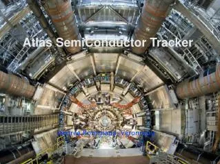
Semiconductor Tracker (SCT) • 4 barrel layers, 9 disks per end-cap • 4088 modules, 6.3M channels (61 m2) • Intrinsic Resolution = 17 μm / 580 μm (Rϕ/z) • Operational T = -8ºC to ~5ºC • C3F8Evaporative Cooling, in common with Pixel detector Ewa Stanecka: Vertex2013
SCT modules 2112 barrel modules • one shape • Back-to-back sensors glued to highly thermally conductive substrates for mechanical thermal stability, wire-bonded to form ~12cm long strips • 40mrad stereo angle between strips on opposite sides • 1536 channels (768 on each side) • 5.6W/module (rising to ~10W after 10 yrs LHC) • up to 500V sensor bias (nominal 150V) • Readout by 12 rad-hard ASICs (binary hit-no-hit) 1976 end-cap modules • 3 shapes Ewa Stanecka: Vertex2013
LHC/ATLAS data taking • LHC delivered: • 48,1 pb-1in 2010 • 5,61 fb-1in 2011 • 23,3 fb-1in 2012 • 31,2 nb-1 in 2013 • 50ns bunch spacing. • ATLAS Trigger system selects interesting events. • “Level 1” hardware trigger, rate ~70kHz • Detector subsystems must read out their data at this rate! • Software-based High Level Trigger further reduces rate to 400Hz for data recording. Ewa Stanecka: Vertex2013
LHC/ATLAS data taking • High instantaneous luminosity leads to up to 40 pp interactions per bunch crossing (μ). • High detector occupancy. • Non-zero rate of Single Event Upsets (SEUs) Ewa Stanecka: Vertex2013
SCT data taking • 99% of readout channels operational • SCT bias voltage maintained at safe 50V level until “Stable Beams” declared, at which point HV is ramped to 150V. • Automated action in 2012, though with shifter oversight. • Automatic recovery (reconfiguration) of modules giving persistent readout errors. • Reconfiguration of all modules every 30 minutes during running (recover from SEUs). Ewa Stanecka: Vertex2013
Evolution of SCT configuration Ewa Stanecka: Vertex2013
SCT Efficiency • Define intrinsic hit efficiency as “hits-per-possible-hit”, i.e. ignore non-operational modules from both numerator and denominator. • To measure efficiency of each module side, perform track fits ignoring that side, and then see if we see a hit. Efficiency well above 99% for all layers+sides! Ewa Stanecka: Vertex2013
SCT single Hit Efficiency • The mean intrinsic hit efficiency for each layer of the SCT measured in 8 TeV proton-proton collisions. • Taken from a special run in 2012 with a low number of p-p interactions per crossing. EwaStanecka: Vertex2013
SCT Noise • Too many fake hits from noise could impair the pattern recognition in tracking software. • SCT was designed to have noise occupancy lower than 5x10⁻⁴. • Occupancy can be measured either in standalone calibration runs, or as part of normal ATLAS data-taking (look in empty bunch-crossings). • Noise is well within design limits. Ewa Stanecka: Vertex2013
Evolution of SCT Noise and Gain Ewa Stanecka: Vertex2013
Pixel data taking • 99.9% Pixel data taking efficiency in 2012 • 95% of the modules are active in data taking in 2012 • Inoperable fraction gets • addressed in the LS1 repairs Ewa Stanecka: Vertex2013
Readout limitations • In case of high burst data rate or SEUs module busies, timeouts and desynchronization are frequent • Mitigated by real-time recovery actions, resulting in great reduction of dead time: O(s) → O(ms) • Module desynchronization addressed by automatic reconfiguration of the affected module. Limitations will be removed by the installation of new ROD/BOC system for Layer 2 which provide higher through-put. Ewa Stanecka: Vertex2013
Pixel threshold and noise Threshold and noise is determined by measuring the discriminator activation curve as a function of the injected charge • The Pixel Detector is operated at a threshold of 3500 e-, typical dispersion 40 e-. • Typical noise is since the beginning below 200 e- for regular sized pixels. • Online Noise Mask of Pixels with noise occupancy > 10-6hits/event • Noise occupancy O(10-9) hits/pixel/beam crossing(after masking) Ewa Stanecka: Vertex2013
Pixel Time-over-threshold (ToT) • Time-over-threshold (ToT, length of discriminator signal) information (in units of 25 ns) is read out together with the hit information → measurement of the deposited charge • Time-over-threshold tuned pixel by pixel to 30 BC @ 20ke • The ToT resolution achieved with the internal calibration is sufficient to distinguish p from K in minimum bias events below 1 GeV/c. The dE/dx resolution is 12% Ewa Stanecka: Vertex2013
Pixel Hit-to-Track Association Efficiency In all active modules including dead and masked pixels • Efficiency ~99% for nearly all parts • Slightly lower efficiency in the outermost discs due to individual modules Ewa Stanecka: Vertex2013
Radiation damage Expected Radiation Dose and Depletion Voltage Shift – Status as of End 2012 Ewa Stanecka: Vertex2013
SCT Radiation damage Evolution of Leakage current in SCT Barrels compared to a prediction Radiation damage is not yet having a significant impact on the operating characteristics of SCT modules. Ewa Stanecka: Vertex2013
Pixel Radiation Damage Cooling stops • Radiation damage in sensor visible in leakage current and shift of depletion voltage • Type inversion happened early 2012 for B-Layer, late 2012 for Layer 1 and not yet for Layer 2 • Depletion voltage/depth can be determined by • using crosstalk method before type inversion • track depth method after type inversion Ewa Stanecka: Vertex2013
Tracking performance Up to 4,000 tracks per event in high-pile-up conditions seen in 2012! • Excellent agreement between data and Monte Carlo simulation. Ewa Stanecka: Vertex2013
Impact parameter and vertex reconstruction • Precise track resolution of the ATLAS Inner Detector result in an transverse impact parameter of O(10)μm • Very good vertex and secondary vertices position resolution Ewa Stanecka: Vertex2013
Inner Detector Radiology Secondary hadron vertex distribution is used for accurate material map Ewa Stanecka: Vertex2013
Technical stop activities - SCT • SCT power and cooling were switched off in February 2013 • Cooling and powering of SCT is expected to return in Mid 2014 • Numerous SCT consolidation activities • Upgrade/expansion of SCT-DAQ • Installation of an additional 38 Read-Out Drivers (RODs) • These will remove a critical DAQ bottleneck and will allow us to be able to read out the SCT up to 3x1034 cm-2s-1(assuming 25ns bunch spacing) • Installation of new TX optical engines in the Back Of Crate (BOC) cards • ROD firmware upgrade Ewa Stanecka: Vertex2013
Technical stop activities - Pixel • Pixel Detector was extracted from the ATLAS detector in the beginning of LS1and since April 2013 is in a lab on the surface for refurbishment • New Pixel Quarter Service Panels nSQP will be integrated into the Pixel detector, after the old services have been dismounted • New position of opto-boards allows maintenance each year • allow Layer 1 readout speed upgrade to 160 Mbit/s • Layer 2 DAQ Upgrade: • operate single link at 80 Mbit/s • additional off-detector hardware will be installed (ROD/BOC) • Install fourth pixel layer: InsertableB-Layer (IBL) at R= 3.3 (see talk by Fabian Huegging on Thursday) Ewa Stanecka: Vertex2013
Technical stop activities – ID common infrastructure • Testing/repair of evaporative heaters system, which ensures thermal shield between silicon detectors and TRT operating in room temperature • Commissioning of new Thermosiphon cooling system which will replace compressor based cooling system • Cleanness: avoiding the pollution produced by working components like compressors and/or pumps. • Leak reduction: due to the reduction of the connections as a direct consequence of the simplification of the main loop. • Accessibility: allows a full time access for preventive and corrective maintenance to all the active parts of the system. • Reliability: increases the reliability using standard industrial material for the Chiller and passive components for the main loop Ewa Stanecka: Vertex2013
Conclusions • The Pixel detector and SCT have performed extremely well during LHC Run 1 and have contributed to the rich and diverse program of ATLAS physics. • Efficiency and noise match or exceed design specifications. • We have put great emphasis on configuration stability reliability and up time during operations. • The effects of radiation damage (increase in leakage currents) are entirely consistent with our expectations (Hamburg/Dortmund model) . • Excellent combined tracking performance. • Ongoing upgrades and consolidation of SCT and Pixel detector during the first long shut-down of the LHC to improve the cooling system and expand the DAQ system to be able to cope with 3 times the design luminosity. Ewa Stanecka: Vertex2013