Download
1 / 64
640 likes | 705 Views
Revolutionary Aerospace Systems Concepts – Academic Linkage Conference May 18-21, 2003. Potential Problem. Space station manned with a 3 member crew Critical failure requires an EVA Today ’ s solution to fix problem: Astronaut Emergency EVA Requires 3 crew members

E N D
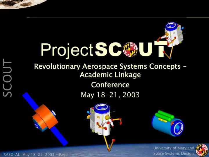
Revolutionary Aerospace Systems Concepts – Academic Linkage Conference May 18-21, 2003
Potential Problem • Space station manned with a 3 member crew • Critical failure requires an EVA • Today’s solution to fix problem: • Astronaut Emergency EVA • Requires 3 crew members • First maneuvers Remote Manipulator System (RMS) to location • Low speed/ lengthy process - Loaded: 0.06m/sec (2.4in/sec) • Immediate operation initiation required • Second and Third must head to airlock for pre-breathing • Time required: 4 hours • One crew member maneuvered at problem site by RMS • One crew member is a free floater • Leaves no one to operate the station Example Scenario: Intelsat rescue mission (3 crew out for EVA)
Today’s Solution • Limitations to this solution • RMS maneuvering time if far away from problem area • Astronaut pre-breathing time • Use of all crew members • No one left to take care of space station • Limited time available for the EVA • Potential Improvements • Not using all crew members • Minimal preparation and travel time • Fix problem faster • Maximize work time Future solution: a system that combines human and robotic interfaces to improve all current systems ILC Dover
Space Construction & Orbital Utility Transport • Proposed element of the Orbital Aggregation & Space Infrastructure Systems (OASIS) program • Designed to operate with proposed Gateway Station at the Earth-Moon L1 Point • Closed-cabin atmospheric system for EVA • SCOUT System: • Two SCOUT pods • Docking Module (DM) • eXtended Mission Pallet (XMP)
Overview • Design Requirements/ Constraints • SCOUT Systems Summary • Mission Planning • Support Infrastructure • Task Requirements • Interior/ Exterior Features • Life Support and Human Factors • Structures/ Thermal • Propulsion/ RCS • Power/ Avionics • Costing • EVA Systems Comparison • Conclusions
Level One Design Requirements • Vehicle requirements • Operate from the L1 Gateway system • Interact with worksite using hands and dexterous manipulators • Attach to and control the worksite (reference worksite: HST) • Provide low-contamination propulsion system for use in contamination-critical regions • Provide for on-board human control, on-board autonomous control, supervisory control, and teleoperation • Single-interface replenishment at the docking port capable of single-person checkout and refurbishment between each use (time < 1 hour) • All safety-critical systems shall be two-fault tolerant • Support extended missions • Capability requirements • Provide capability to operate at International Space Station with minimal modifications • Standard operational capabilities shall meet or exceed EVA capabilities demonstrated on HST and ISS • System requirements • Design in accordance with NASA Standard JSC-28354, Human-Rating Requirements • Minimum TRL of 3 by Jan. 1, 2005 and minimum TRL of 6 by Jan.1, 2008 • Launch on US launch vehicles currently planned to be operational in 2005
SCOUT Major Design Constraints • Task/human arm interaction • Worksite attach/control • Zero pre-breathe • Shirt-sleeve operation • Operating Pressure: 8.3 psi • RMS attach fitting • International Berthing and Docking Mechanism (IBDM) with internal hatch opening • Escape system placement
Basic SCOUT Dimensions 1.50 0.87 2.00 0.75 0.70 r = 0.33 0.34 1.85 0.82 Rear View Bottom View Side View All dimensions in meters
Trajectory to L1 1 4 2 3 5 Lin, Frank. Lunar L1 Gateway & SEP Design Briefing. 02 Nov 2001. • Test Mission at ISS • Solar Electric Propulsion (SEP) stage travels with SCOUT system • SEP travels with Gateway on autonomous spiral to L1 • Docking Module (DM) and SCOUT are berthed with Gateway • Crew Transfer Vehicle (CTV) brings first six month crew
Docking Module • Three International Berthing and Docking Mechanisms (IBDMs) • Two are used for SCOUT pods • One is used for attachment to Gateway • Storage capabilities • Six months of propellant • Spare batteries • Human suit arms and gloves • Self-sufficient power • Triple junction crystalline solar arrays • Is = 1394W/m2, ρpower = 250W/kg, ηeff = 40% • Surface area = 4.5m2, mass = 10kg • Generates 5kW
Resupply Plan • SCOUT vehicles are designed to automatically resupply fuel, atmospheric consumables, and power after each sortie during DM attachment • Docking Module resupply • Every six months for a nominal mission model • Every three months for an aggressive mission model • OASIS infrastructure vehicles • Crew Transfer Vehicle (CTV) rotates crew and carries human consumables every six months, and life support every two years • Hybrid Propellant Module (HPM) resupplies LOX and LH2 every six months • Chemical Transfer Module (CTM) ferries payloads short distances, provides a high impulse transfer from LEO to L1, and is used for extended missions
SCOUT System Reliability • Cumulative probability of safe crew return over the life of the program must exceed 0.99 • Assumptions: • Pod failure will force bailout of astronaut • Astronaut must rely on independent propulsion system for safe return to Gateway • Escape components consist of a Bailout System (BS) and Propulsion Equipped Bailout System (PEBS) • After examining several combinations of pods and escape systems, it was determined that two pods each with a PEBS provided the required reliability
Nominal and Aggressive Missions • Nominal six-month mission consists of 30 sorties between both pods • Eleven hours spent in the pod for eight hours of work • Total SCOUT hours for two pods: 240 working hours and 330 hours inside the pod • Pod end of life occurs at 20 years • Aggressive mission model doubles sortie and resupply rates Example Sortie
Extended Duration Missions • Several possible scenarios • Geostationary satellite servicing • Lunar orbit • Mars mission • ISS servicing • Example mission model from L1 to lunar orbit • SCOUT is not designed to land on the lunar surface • CTV stack carries SCOUT and XMP that transports propellant and consumables • Approximate travel time of 23 hours • CTV acts as lifeboat in the case of an emergency • Tasks are completed in a 16 hour workday which includes work time and breaks
eXtended Mission Pallet (XMP) • Supports off-site extended sorties: • Attaches between SCOUT and tow-vehicle • Remains attached to tow-vehicle while SCOUT performs worksite operation • Provides off-site refueling/recharging • Shirt-sleeve atmosphere allows passage from SCOUT to tow-vehicle • Mission Flexibility: • May be tailored to particular extended mission • IBDM permits docking with any OASIS vehicle
Task Requirements • Meet or exceed EVA capabilities demonstrated in International Space Station (ISS) and Hubble Space Telescope (HST) operations • Orbital Replacement Units (ORUs) • Large truss segments • Modules • Flexible materials • Fragile materials • Assembly of a 25m infrared telescope • Truss segments • Fragile materials • Refueling • Lunar lander, CTV, CTM, HPM, SEP, and Gateway station maintenance • ORUs • Fragile materials • Service on other SCOUT pods, the DM, and XMP • ORUs • Fragile materials
Dexterous Manipulator Design • Task arms are modeled after 8-DOF Ranger Telerobotic Shuttle Experiment arm • Trade study found two arms to be the best choice • One arm did not provide the ability to grasp the hardware being removed while removing bolts and latches • Three arms brought a concern about the interference of the arms with each other and with the human arms due to intersecting work envelopes • Uses interchangeable end effectors for task completion • Maximum of eight end effectors on SCOUT • End effectors will be predetermined prior to sortie • Grapple arm is a modified version of the task arm • Has a pitch joint at the wrist and is longer than the task arm • Uses either a universal gripping end effector or a foot restraint interface end effector • Laser rangefinder is mounted on the grapple arm elbow
Example End Effector Set • Bare Bolt Drive (BBD) end effector • Drive bolts for the insertion and extraction of ORUs and the assembly of truss structures • Parallel Jaw Mechanism (PJM) end effector • ORU grasping interfaces referenced from the ISS Robotic Systems Integration Standards (JSC-37996) • Different “fingers” depending upon the grasping surface • Hand-over-hand (HOH) fingers • Conceptual design that has the ability to grip several different items with set dimensions and shapes • Found on the grapple arm and task arms • Used for gripping the worksite and non-thrusting maneuvers • Microconical end effector (MEE) • ORU grasping interfaces referenced from the ISS Robotic Systems Integration Standards (JSC-37996) • Used to grip microconical interfaces and micro fixtures found on ORUs less than 600kg • End effectors are stored on tool posts found on both the sides and underneath SCOUT
Comparison of Tool Sets O’Hara, John M. et al. Extravehicular Activities Limitations Study. ( all except * )
Exterior Features Helmet/ Heads-Up-Display (HUD) External Camera Lights External Camera Single Hydrazine IBDM Nitrogen Quad Handrail Hydrazine Triad Star Tracker Human AX-5 Arms UHF Task Arms Ka-Band Radiator Mini-Workstation Radiator Tool Posts Grapple Arm Escape System RMS Grapple Fixture Laser Rangefinder Front View Rear View
Secondary Egress / Bailout (SHEEP) • Current bailout design is an externally expandable hybrid spacesuit, to be known as the SCOUT Hybrid Expandable Escape Pod (SHEEP) • Hybrid design of the current NASA bailout ball, and the past Rockwell conceptual design of the Rib Stiffened Expandable Escape System (RSEES) • Escape Pod would be contained within a canister that is located on the outside of SCOUT • In the event of an emergency, the crewmember would deploy the spacesuit, climb in, close the suit, and detach from SCOUT • Allows the crewmember minimal use of their hands in order to control the propulsion device and translate along EVA handrails • Provide crew member with 3 hrs of emergency air (back-up from SCOUT) Viewing window SAFER-type propulsion system Hand Controller Spacesuit Arms Soft expandable body
Contoured Hull • The contoured torso hull will be place on the relative front of SCOUT and be aligned with the relative top of the vehicle • The design of the torso hull was based off the torso of other hard suits, more precisely the JSC Mark III and Ames AX-5 • Combination of two rotary seals will be used to accommodate the varying shoulder berths and sizes of the wide range of users • Current design for spacesuit arms and gloves • Modeled after the NASA Ames AX-5 suit arms • Shuttle Transport System (STS) Extravehicular Mobility Unit (EMU) gloves • Development of the AX-5 suit is based on the capability of providing the crewmember with a zero pre-breathe mission through an operating pressure of 8.3psi
Internal Layout Touch Screen Monitors Hand Controllers Internal Camera CO2/Air System Pressure Control Storage Box Escape Hatch Keyboard Fire Extinguisher Waste Collection System Computers Foot restraint locations Side View Front View Rear View
Internal Volume Constraints • Major volume requirements designed into the cabin layout • Minimal volume required to accommodate a 95% American male • 0.72m x 0.71m x 0.172m • Internal components placed around this volume • Minimal volume required for a controlled tumble • Sphere with 1.22m diameter • Needed to flip over within SCOUT
Worksite Interaction • Heads-Up Display (HUD) • Used for display of pertinent information dealing with • Flight control • Robotic control • General SCOUT system • Hand Controllers • Two 3-DOF controllers used for translation and rotation control of • Manual flight • Operation of the task arms • AX-5 Arm and Glove Sensors • Used to control task arms • Activated/deactivated by voice command • Voice Recognition • System utilizes pre-allocated communications hardware with the computers to process voice commands • Allows for both coarse and fine control of dexterous manipulators HUD Hand Controllers
Foot Restraints – Floor Operation used for AX-5 suit arm task work Glove Sensors Voice activation Foot Restraints – Back Wall Operation used for Hand controllers Voice activation Crew Member Orientation
Command, Control, and Comm Station • Two Touch Screen Monitors • 15in display • Mass: 7.3kg • Peak Power: 26W • Accepts both HDTV and computer input • Primarily used as a reconfigurable computer display during system monitoring and video communication • Keyboard • Internal Camera • Used for real-time video conferencing Touch Screen Monitors Keyboard Camera Comm Station
Life Support Systems Flowchart Legend: - Air Systems - Vacuum - Gateway - Waste - Pumps - Fan Overboard Vent Charcoal Bed Filter Metox Pressure Control Panel (PCP) Cabin Condensing Heat Exchanger Water in 57kPa (8.3psi) 43% O2 / 57% N2 Waste Water Tank Water out Waste Collection System Air Tanks 20.7MPa (3000psi) To Gateway
Food, Water, and Waste • Food • Nominal one meal per day on SCOUT • Nutrition requirements • Protein: 150g/day • Carbohydrate: 350g/day • Lipids: 85g/day • Water • 3.1kg (105oz) of water carried on board in a standard reusable drink container • Waste • Smaller version of Shuttle WCS • Convenient • Use does not require deviation from nominal diet
Atmosphere 2 1.8 1.6 ISS: ppN2 = 11.6, 1.4 Acceptable below this line R = 1.39 1.2 Ideal below this line R 1 0.8 Gateway: 0.6 ppN2 = 5.4, 0.4 R = 0.65 0.2 0 0 2 4 6 8 10 12 14 16 ppN2 2 • Air Systems provides nominal 20.5 hours; 41 hours as absolute maximum • One oxygen tank is emergency backup • Operating pressure 57kPa (8.3psi), 43% O2 / 57% N2 • R = ppN2-bloodstream/Patm = 0.65 (zero pre-breathe) R Value for Various Nitrogen Partial Pressures of Stations Hosting SCOUT
Overall Structural Design • Hexagonal Pressure Hull • Load-bearing aluminum panels incorporating Micrometeoroid (MM) and Orbital Debris (OD) protection • Stringers to transfer panel loads and serve as hard attachment points for Shuttle launching • Outer Frame • Load-bearing aluminum panels with MM and OD protection • House external tanks and electronics • Back panel hinged for Li-Ion Battery replacement and Power Distribution Unit (PDU) servicing • Main mechanisms • International Berthing and Docking Mechanism (IBDM) • Dexterous Manipulators • Remote Manipulator System (RMS)
Launch Vehicle Integration • Using Spacelab Logistics Pallet (SLP) with 5 point attachment: • 2 sill fittings ±X and ±Z loads • 2 sill fittings ±Z loads • 1 keel fitting ±Y loads • Other SCOUT, Docking Module (DM) and eXtended Mission Pallet (XMP) attached to pallet similarly
Loading Configuration - Launch Z Y X • Considered • Major inertia loads • All components over 2kg considered • Components masses multiplied by shuttle launch loads • X = 5.8g, Y = 4.85g, Z = 8.5g • Forces in 350N – 20kN range • Pressure load • Pressurized at 101.3kPa (14.7psi) • Not considered • Assumed smaller compared to launch induced loads • Launch acoustics • Random launch vibration • Thermal variation
Loading Configuration - Operation • Pressure • Design load: 101.3kPa (14.7psi) (departing from ISS) • Other loads: 62kPa (departing from Gateway), 57kPa (operating at worksite) • Task arms • 2620N force, 374N-m bending moment, 52.2N-m torque • At shoulder mount, in best case position • Grapple arm • 400N tensile force, 400N shear force, 1170N-m bending moment and torque • At shoulder mount, from various worst case configurations induced by task arm forces • Human arms • 1140N force, max force exerted by 95% male upper arm in space suit (NASA-STD-3000) • At shoulder mount of AX-5 arms • Remote Manipulator System (RMS) • 890N, 20º off perpendicular to grapple shaft (on back)
Loading Configuration - Other • Worksite transfer • Thrusters forces on the order of 1N and 6N • Docking • IBDM docking loads ~120N • Maximum docking velocity = 0.06m/s • Assumed 1 second impulse load • Berthing, if using RMS • Already accounted for in operational loading configuration • Quantification of loads resulted in analysis of only two configurations • Shuttle launch / abort • Worksite operation
Micrometeoroid and Orbital Debris Protection • Definitions of Terms • Micrometeoroid = 10-18 – 1.0gm in mass [NASA PD-EC-1107] • Natural origin • Orbital/Space Debris exist below 2,000km altitude (LEO) • Artificial objects • Requirement • The design shall provide a minimum Probability of No Penetration (PNP) defined by: • Bumper Wall (Outer Wall) • Aluminum 6061-T6 • Thickness: 0.06cm • Back-Up Wall (Inner Wall) • Aluminum 6061-T6 • Spacing = 1.0cm • Thickness: minimum of 0.24cm required A = exposed surface area (m2) Y = exposure time (year) PNP=0.9999AY Requirement for Space Shuttle Payload [NASA SSP-52005B]
Radiation Exposure Limits • Assuming annual radiation exposure to Blood Forming Organs (BFOs) • 50 allowable rem / 365 days = 0.14rem/day • (0.14rem/day) / (24hrs/day) =0.007 allowable rem/hr • Estimated total time in pod per astronaut • (6mo)(15days/6mo)(13hrs/day) =195hrs • Total allowed radiation exposure • (0.007rem/hr)(195hrs) = 1.4 allowable rem • With 4g/cm2 aluminum shielding data from STS-89 • 62 days exposure = 0.6% increase in excess fatal cancer • With 4g/cm2 aluminum shielding data from SCOUT • 15 days exposure ~ 0.2%increasein excess fatal cancer≪ 3% lifetime limit • Assuming Gateway radiation levels ≤ SCOUT180 days exposure ~1.74% increase in excess fatal cancer (3% lifetime limit) *Radiation limits gathered from NASA-STD-3000
Radiation Protection • Panels that need extra radiation protection • Front, extra 3.23g/cm2 • Left Front, extra 2.42g/cm2 • Right Front, extra 2.23g/cm2 • These numbers are to meet the requirement of having radiation protection of 4g/cm2 • The current plan for SCOUT for the Gateway missions is to have these panels as extra aluminum panels • This increases the margin of safety (MOS) for those panels of the spacecraft • All other areas of the spacecraft have enough mass and surface area of other components that no extra radiation protection is required • With future innovation in radiation protection, the front 3 panels can be outfitted with any material that will meet the above criteria • Also for missions that may require more stringent radiation requirements, SCOUT can have panels added in locations requiring more protection
Calculations Overview • Calculations were done to determine the thickness of the SCOUT panels • Three different situations were analyzed • Pressurization loading • Operational loading • Launch loading • Axial direction • Shear direction • Each system was optimized to the minimum thickness based on the lowest non-negative margin of safety (MOS) that was acceptable for all requirements • Micrometeoroid, orbital debris and radiation protection were taken into account for these calculations
Panel Structure Factor of Safety – 2.0 : Primary
Panel Structure Factor of Safety – 2.0 : Primary
Thermal Control • Interior Environment • The interior of the pod, specifically the pressure hull, will be maintained thermally by utilizing a series of different systems • Heat Exchanger: transfer heat from circulating ‘cabin’ air to working fluid in heat pipe • Heat Pipe: transport heat to radiator using freon via capillary action • Radiator: radiate heat to space • Heater: trim temperature during colder conditions • Battery Subsystem • The batteries will be controlled thermally by an active radiator system • Radiator: radiate heat generated from battery packs using a system of cooling loops and a working fluid consisting of freon • Pump: circulate freon through radiator • Insulation will be used to keep the fuel tanks at nominal temperature with Multi-Layer Insulation (MLI)
Propulsion Tanks Nitrogen Propellant t = 0.013m L = 1.6m Lt = 2m Mass = 98kg Hydrazine Propellant t = 0.002m L = 0.33m Lt = 0.5m Mass = 1.8kg Lt L t • Requirements for tanks Nitrogen Pressurant t = 0.0071m L = 0.09m Lt = 0.3m Mass = 1.7kg * 2 tanks of each per SCOUT
Pressure Lines and Tank Attachments • Pressure lines • A similar analyses as the tankage MER analysis has been conducted with a factor of safety of 4 • Diaphragms with thickness t = 0.002m • Tank Structural Attachments • Pads and Rods/Hooks • Estimated 2% of the supported weight • Support for Nitrogen Propellant = 3.78kg • Support for Hydrazine Propellant = 0.10kg • Support for Nitrogen Pressurant = 0.63kg = 0.234kg Md=rVd Vd=(4/3)π[ri3-(ri-0.002)3] Rods Pads
Tank and Thruster Placement • 16, 1N Nitrogen thrusters • For contamination-critical sites • 4 quads • 16, 6N Hydrazine thrusters • For non-sensitive sites • 4 triads • 4 singles Nitrogen Propellant Tanks Nitrogen Pressurant Tank * One on each side Hydrazine Propellant Tank * One on each side
Hydrazine System Schematic Fill and Drain Valve Flow Control Valve Normally Closed Flow Control Valve Normally Open Filter Thrust Chamber Valve (TCV) Valve Branch A Valve Branch B Heater Pressure Temperature Thruster Isolation Valve (P) (T) Top Right Panel Top Left Panel (P) (P) (T4) (T8) GN2 GN2 (T) (T) (T2) (T6) (T3) (T7) (P) N2H4 N2H4 (T) (T1) (T5) (P) (T) Bottom Right Panel Bottom Left Panel 4B 4A 1A 1B (T12) (T16) 2 (T10) (T14) 5 3A 6B 6A 3B (T11) (T15) (T9) (T13) Valve Heaters Line Heaters Catalyst Bed Heaters
SCOUT Power System Capabilities Power system requirements summary: Li-Ion nominal operation mode (3 battery systems):
Power Distribution Block Diagram Firewire Data Bus Firewire Data Bus FDCC FDCC FDCC Solid State Recorder Solid State Recorder Li-Ion Battery Docking Module Power Resupply Standard Power Systems (28 VDC) Power Distribution Unit A Low Power Components Power Distribution Unit B CompactPCI Bus Power Distribution Unit C Robotic Control Legend: FDCC - Flight & Data Control Computer - Primary Avionics Components - Critical Crew Survival Systems - Mission Systems - Data Transfer - Power Transfer • PDU: • Modulated for easy reconfiguration to meet specific requirements • Capable of providing 97% efficiency at 1500W • Space qualified on several spacecraft
Avionics Top-Level Block Diagram Communication/ Video System Attitude Sensors Life Support Sensors Propulsion System Power Distribution Astronaut Interface Firewire Data Bus Thermal Control Firewire Data Bus CompactPCI Bus Robotic Control FDCC FDCC FDCC Computer Display Solid State Recorder Solid State Recorder Computer Display Legend: FDCC - Flight & Data Control Computer - Primary Avionics Components - Critical Crew Survival Systems - Flight Control Systems - Mission Systems