Download
1 / 16
160 likes | 248 Views
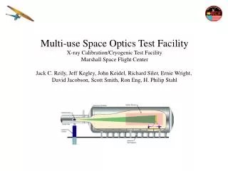
Facility Advisory Committee BFW Calibration Test Results. on behalf of: Jim Bailey Keith Caban Clive Field Geovanni Gordon Tom Nakashima Danny Peterswright Reggie Rogers Donald Schafer Yung-Yung Sung. BFW Assembly Mounted on Adjustable Support. Electrical Connectors for Wire Signals.

E N D
Facility Advisory CommitteeBFW Calibration Test Results on behalf of: Jim Bailey Keith Caban Clive Field Geovanni Gordon Tom Nakashima Danny Peterswright Reggie Rogers Donald Schafer Yung-Yung Sung
BFW Assembly Mounted on Adjustable Support Electrical Connectors for Wire Signals Potentiometer Pneumatic Solenoid Valve Compression Spring Positioner Air Supply Shut Off Valve Precision Screw Card Position Monitor (Limit switches) Frame Housing Alignment Fiducials Pneumatic Cylinder (Modified since) Vacuum Pump Connector (2.75” Conflat Flange) Vacuum Chamber Connection Flange (NW-50 CeFix w/Clamp) Adjustable Mounting Support Beam Port Assembly model courtesy: J. Bailey, ANL
BFW Card Prototype Drawing X-wire end point: 39.614 mm Beam center: 40 mm Gap between beam and X-wire: 0.386 mm Prototype material: Al-6061 Actual material: Macor Thickness: 3/16” (4.8 mm) Coating: Kovar [tooling in progress] Y-wire end point: 37.014 mm Beam center: 37.2 mm Gap between beam and Y-wire: 0.186 mm Courtesy: C. Field, R. Rogers
BFW Card Wiring: Tooling Micrometer stage BFW Card Rods for hanging BFW wire with weights Card holder ‘Carbon wire & weight’ Copper Tabs • Wires soldered to copper tabs • Wires from copper tabs connect to BFW feedthrough • Feedthrough to be grounded and RF shielded Courtesy: C. Field, Y.Sung
BFW Alignment Procedure at SLAC(outside Vacuum) • Coordinate system definition • Wire card positioning and alignment • Transformation Factor from BFW tooling balls wire card QC Instruction List
BFW Alignment Procedure (in Vacuum) • Wire position found using TB values • Repeatability check • Wire position check in virtual beamline coordinate system QC Instruction List
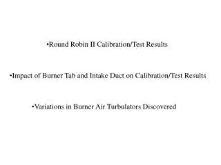
BFW Test: Sample ‘Good’ Data, BFW #7 All Data, courtesy: SLAC QC, E. Lundahl, K. Caban, T. Nakashima
BFW Test: Sample Data, BFW #12Vacuum Test 1 • Measurement Method: • Under Vacuum • 200 cycles, 10 measurements, Random sampling • Relaxation time between cycles: ~ 1 second
Measurement Method: • Under Vacuum • Another 10 cycles, 10 measurements, Consecutive sampling • Relaxation time between cycles: ~ 1 minute BFW Test: Sample Data, BFW #12Vacuum Test 2 • BFW #12 RFI-ed • Tested for repeatability at ANL (All units are tested at ANL) • Wire position verified at SLAC • Wire repeatability verified with delayed cycles (small sample size) at SLAC • SLAC Procedure to calibrate devices using small sample size + delayed cycle measurement
BFW : Status Reminder Process Time per Assembly: ~ 1 day
Top View ¼-20-UNC Screws 1 and 2 ¼-20-UNC Screws 3 and 4 This precision screw remains fixed Socket head screw loosens and tightens collar on precision screws Socket head for adjusting the precision screws Y-Precision Screws 10, 11, and 12 ¼-20-UNC Screws 5, 6 and 7 (Brass washers under heads are not shown) X-Precision Screws. Do not touch Assembly model courtesy: J. Bailey, ANL
BFW Assembly (Body Sectioned) Wire Card Down in Inactive Mode Potentiometer (Out Position) Electrical Connectors (Down Position) Internal Return Spring (Expanded Position) Internal Kinematic Stop Plates (Open Position) Pneumatic Solenoid Valve (Cylinder Vent Position) Lower Limit Switch (Actuated Position) Bellows Seal (Compressed Position) Wire card (Down Position) BEAM Assembly model courtesy: J. Bailey, ANL