Download
1 / 23
230 likes | 391 Views
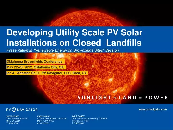
Developing Utility Scale PV Solar Installations on Closed Landfills Presentation in “Renewable Energy on Brownfields Sites” Session. Oklahoma Brownfields Conference. May 22-23, 2012. Oklahoma City, OK. Ian A. Webster, Sc.D., PV Navigator, LLC, Brea, CA.

E N D
Developing Utility Scale PV Solar Installations on Closed LandfillsPresentation in “Renewable Energy on Brownfields Sites” Session Oklahoma Brownfields Conference May 22-23, 2012. Oklahoma City, OK Ian A. Webster, Sc.D., PV Navigator, LLC, Brea, CA S U N L I G H T + L A N D = P O W E R www.pvnavigator.com GULF COAST 10497 Town and Country Way, Suite 830 Houston, TX 77024 713.468.5886 WEST COAST 1 Pointe Drive, Suite 320 Brea, CA 92821 714.388.1800 EAST COAST 5 Great Valley Parkway, Suite 350 Malvern, PA 19355 610.251.6851
Project Navigator, Ltd.’s, PV Navigator, L.L.C. Has Grown a Landfill-Specific, Solar Power Development Group Since 2007. What • PVN develops MW-scale, PV installations on landfills and Brownfields sites • Typically fixed-tilt, rack-mounted, self-ballasted installations • Approximately 50 MW of site capacity under Option • More than 300 MW in overall PVN pipeline Who • PVN is a wholly-owned subsidiary of Project Navigator, Ltd. (www.ProjectNavigator.com) • Internally financed (to date) • Staffed by engineers, land development and power experts • 4 year growth and branding effort • Relationships with Enel, Gestamp and Chevron Energy Solutions • Where • Projects primarily in CA and NJ • Caribbean expansion goals • How • Detailed sites/landfill locations knowledge • Knowledge of Fortune 500 boneyard acreage • Excellent regulatory relationships • Landfill post closure PV permitting expertise • Leverage proven PV technologies and apply to landfills • (e.g. PVN’s California Energy Commission Grant) • Growing brand recognition
1 – 10 MW, Small-Scale, Distributed, PV Solar Facilities Can Rapidly Deliver Power to Meet Utilities’ RPS Standards or Generate Renewable Energy Credits (SRECs). PV Navigator, L.L.C.’s solar development business is centered around the following drivers: • Speed to marketplaceahead of larger central-scale projects • Availability of urban landfill or Brownfield siteswhich can host the panels • Availability of fundingfor small plants • Location of sites by existing distribution or local load • Project cost avoidancevia use of Brownfield sites and the need for new transmission lines • Minimizing permitting requirementsvia development on State or Federal superfund sites • RPS regulatory driversfor green power purchase • e.g., in CA, 20% renewable power by 2010, and 33% by 2020 Costs and project risks associated with central-scale projects and associated transmission are eliminated PVNavigator’s business area Local Substations Consumption Conventional Generation Long Distance Transmission PVNavigator Strategy Brightline Local distribution • Brownfield site or Landfill • Urban location • Close to power consumption point • Local transmission Present Day Large Desert PV Plants
PVN’s Solar Development Projects. Buena Vista Landfill: 1MW NH West Coast OR VT Avon Refinery: 10 MW Purity Landfill: 1MW OII Landfill: 4MW BKK Landfill: 10MW WDI Landfill: 4MW Big Bear Landfill: 2MW Gemcor Site (Chevron Landfill): 10MW Milliken Landfill: 5MW Barstow Landfill: 10MW ID MA RI NY CT NV 1 2 NJ Avon Refinery: 10MW PA CA 12 13 OII Landfill: 4MW East Coast 14 9 10 Buena Vista Landfill: 1MW Delaware City: 4MW Ocean Township: 5.86MW Lumberton Landfill: 2.4 MW Owens Corning Landfill: 3.1 MW 3 4 8 6 11 5 BKK Landfill: 10MW 7 MD AZ DE
Key Partnerships Have Been Formed to Grow the Business.CES Providing EPC Capabilities and Interconnect Feasibility.
While Large Scale (300 MW and up) Solar Facilities Are Planned for the U.S. Southwest, They Face Permitting, Financing, and Interconnect Challenges. Not so for Urban Located Landfill or Brownfield Sites. Landfill Gas-to-Power Perforated Gas Pipe Typical Landfill 20 to 200 acres Methane and Carbon Dioxide Methane and Carbon Dioxide Breakdown Process of Landfill Waste Waste/ Complex Organics Landfill gas (LFG) migrates to waste prism extraction wells and the associated collection systems. The LFG is conveyed via a network of pipes to feed a power generation plant. Organic Acids Blower & Flare Station Landfill Gas Landfill Gas Collection Wells in Waste Power Generation via Gas Turbine or Steam Cycle Systems Other Landfill Monitoring Systems (e.g. for groundwater)
Landfill Sites are Excellent Platforms for PV Solar Facilities. Flat Acreage, Close to Load and Interconnect, Putting Otherwise Unusable Acreage Back to Use. Projects are Technically Straightforward but Administratively Complex. The sun gives off about 400 trillion watts of power Photovoltaic Cell Detailed cross-section PV Solar Power • A photovoltaic (or PV) cell is a specially treated wafer of silicon, sandwiched between two thin contact plates. The top contact is positively charged and the back contact is negatively charged, making it a semiconductor. • The n-type semiconductor has an abundance of electrons, giving it a negative charge, while the p-type semiconductor is positively charged. • Electron movement at the p-n junction produces an electric field that allows only electrons to flow from the p-type layer to the n-type layer. • When sunlight hits the solar cell, its energy knocks electrons loose from the atoms in the semiconductor. • When the electrons hit the electrical field, they’re shuttled to the top contact plate and become a usable electric current. • PV panels are mounted in racking systems specially designed to accommodate landfill-specific requirements such as “no cap damage” and “waste settlement.” Electric Current Solar Panel Glass covering Not to scale A typical racking module is 10ft. By 20ft. and generates 2.5kW. This translates to about 1MW from every 3-5 acres. Transparent adhesive Anti-reflection coating Landfill Gas-to-Power Utility Company DC/AC Inverter Necessary to convert electric current for consumer use Perforated Gas Pipe Methane and Carbon Dioxide Methane and Carbon Dioxide Solar Power to the Grid Excess energy from the solar array is fed into the power grid. It helps provide extra electricity to the community, especially during peak daytime hours. Waste/ Complex Organics Landfill gas (LFG) migrates to waste prism extraction wells and the associated collection systems. The LFG is conveyed via a network of pipes to feed a power generation plant. Organic Acids Blower & Flare Station Landfill Gas Landfill Gas Collection Wells in Waste Power Generation via Gas Turbine or Steam Cycle Systems Solar Panels Other Landfill Monitoring Systems (e.g. for groundwater) Customers
According to U.S. EPA, There is No Shortage of Brownfield and Landfill Site Acreage Which Could be Suitable for Renewable Energy. • Over 400,000 identified Brownfield sites in the United States • 16 million acres are available for development of renewable energy • That’s enough land to generate approximately 3,175,000 MW • (For reference, the Hoover Dam generates about 2,000 MW)
The Business / Economic Viability of PV Power is Increasing. High electricity prices, combined with… …State-specific renewable portfolio standards (RPS) and … …the gradual annual increases in power prices… Reference: http://www.eia.doe.gov/emeu/steo/pub/gifs/Fig23.gif … will make PV generation competitive with fossil fuel generation. Reference: http://www.7gen.com/node/26000
A Landfill Site is a Good PV Development Candidate if Certain Screening Criteria are Met. Appropriate Geographic Location Land Control (Title or Long-Term Lease) Environmentally Impacted Land (Restricted Future Use) Nearby Interconnection Point • Project Financing • External • Internal Adjacent Load (PPA Approach) Green Corporate Goals State-Mandated Renewable Portfolio Standards
The Stages in PV Solar Power Plant Development.The Challenges Lie in the Front-End Permitting. Site Identification Site Control* Civil Engineer Selection Contract Execution Site Plan / Layout Design Site Upgrades • Early Planning, Negotiations and Project Marketing Phase • Power Purchase Agreement (PPA) Proposal and/or Negotiations • Power Marketing • Interconnect Study • Environmental Permitting Including Any EIR Work and Associated Environmental Document Revisions • Facility Conceptual Design • Project Economic Calculations Technology Provider/EPC Contractor Selection Contract Execution Power Scheme Design Financing Commissioning Operations and Maintenance Procurement Tariff Rate Determination Power Purchase Agreement Execution Inter- connection Agreement Execution Permit Acquisition * Can be in form of an “option agreement” between landowner and solar project developer, or a longer term land lease. Option would convert to a land lease once the scope and economics of the proposed project are better defined, such as at the execution of a PPA.
Key Design Criteria are Minimal Settlement & The Continued Need for Cap Functionality. 3 2 4 1 Types of footings for rigid glass solar panels Design considerations include eliminating cap penetration, continued functionality of the ET cap, storm water management, wind design and insuring protectiveness during an earthquake event. SunPods adjustable footing Pre-cast concrete footing Ballasted racking • Design of PV Array will take into consideration: • Settlement • Total • Differential • Panel placement on cap • Spread footings • Anchors • Continued performance of evapotranspirative (ET) cap • Infiltration minimization • Vegetative growth • Stormwater management • No standing water • Runoff management • Other Electrical lines in above-ground, lightweight, flexible steel conduit SunPods solar array with adjustable footing Settlement monument Drainage swale ET monocover Landfill ET cap designs Swale cross-section design
The Solar Panel Rack’s Design Must Not Damage the Landfill’s Cover and Must Accommodate Future Settlement. 1 2 3 H Degree of Cap Penetration M L Earth Anchors/Auger System Shallow Piers Self Ballasting, Higher Load Type of Racking System REFERENCE: 1. http://www.mass.gov/dep/energy/solarlf.pdf 2. http://aec.army.mil/usaec/newsroom/update/win08/win0812.html 3. http://www.sunpods.com/sunpods-products-and-solutions.html
Case Study: PV Navigator, LLC Entered into an Agreement in 2011 to Develop a 6 MW PV Solar Installation on the Southern Ocean Landfill (SOLF), New Jersey with Power Sales to Atlantic City Electric.
PV Navigator, LLC Leads a Multi-talented Solar Development Team. Systems Engineering, Design/Build Services Project Financing EIR and NEPA Services Project Owner, Manager and Systems Integrator Energy Solutions Technology Supplier: Skid-Mounted PV Solar Systems
Early 2000’s Closure of SOLF is Well-Documented. Information Aids Current PV Development Program. • Key Facts • Operated 1970 – 1989 • Engineered cap in 2003/04 • A & B waste prisms at 14 & 48 acres, respectively • B’s flat top deck is 24 acres • 60 ft depth of trash • Regulated by NJDEP Pre-Closure, Late 1990’s During Closure, Early 2000’s VEGETATION Reference: Southern Ocean landfill Closure Project, As-Built Drawings, Hatch Mott McDonald, June 2004 Post Closure, 2004
Conceptual Layout of Solar Modules for the Southern Ocean Landfill PV Power Development. • CONCEPTUAL PLAN • 2,300 SunPods solar units (each unit 10’x20’) • Total system would be capable of 5.86 MW, generating about 8 MM kW-hrs per year • 30 year operating lifetime (planned) Conceptual Layout of 5.86 MW PV System at the Southern Ocean Landfill Inverter Switch Yard Solar PV Power Layout
Prefabricated, Racked PV Systems Specifically Designed for Landfill Caps Will Be Used at SOLF Development. Features of SunPods Landfill PV Solar Unit • 2.5 kW per array (as shown) • i.e. 400 arrays per MW • Arrives prefabricated • Minimal onsite assembly • 20 ft X 10 ft arrays • Weighs 2,500 lbs, supported on a leveling support system • Eliminates landfill cap penetration • Self ballasting • 10 Gauge steel frame • Rated to 100 mph + wind speed • Ready to connect • Minimal maintenance
PV Rack Support Geotechnical Calculations Show the Waste Prism to be Stable. First data point is at 5 ft bgs Legend* Very Dense and Very Hard N Dense and Hard Medium Dense and Very Stiff Loose and Firm Very Loose and Soft *Ref: Rogers, J.D, 2006, Surface Exploration Using the Standard Penetration Test and the Cone Penetrometer Test, Environmental & Engineering Geoscience, Vol. XII, No.2 pp162
Community Outreach and Project Advocacy is Conducted via Public Meetings…Where Resistance is Typically Low.
Conclusions: Lessons Learned After 5 Years of PV Navigator’s Solar Project Development Efforts • The challenges are in (1) permitting, and (2) finding a power off takerwho’ll pay enough (cents/kW-hr) to make the economics work • Technology and construction challenges are secondary • Have a good (probabilistic?) economic model • Define and negotiate with the potential offtaker(s) early • Perform power interconnect / feasibility study early in the process • Bid the forecasted power from the development into utility RPS RFOs • Regarding landfill post closure use: • If considering a closed landfill, evaluate the quality/quantity of existing site characterization data, esp. “geotech.” Keep costs down by leveraging past info. • Develop solar layout and grading plans early in the process • Cross check solar layout Vs final grades of remedy • Add “solar final use vision” text to appropriate docs to environmental agencies • Develop a project fact sheet, early, and discuss with all possible stakeholders
PNL Has a Grant from the California Energy Commission to Pilot Test a PV System on a Closed Landfill Site in Los Angeles. Software Generated Data Display Goal: The collection of power generation performance data as well as information on any impacts the solar racking system may have on the landfill cap’s functions regarding gas collection and infiltration minimization. Figure shows a small scale, PV solar rack pilot system, located on a landfill cap. The purpose of the pilot unit is to measure and monitor the systems power generation operating performance on a landfill site where prior desk-top calculations have shown the installation of a 1 to 10 MW PV solar facility may be technically and economically viable. The pilot facility would typically be operated from 1 to 2 years, thereby permitting any effects of the solar system on the cap (e.g. in the form of increased load and altered storm water management) to be evaluated. 9 13 1 6 8 7 10 12 WiFi/telemetric system data collection/transmission Reference settlement monument Landfill lateral gas collection system (which may or may not exist for the selected landfill) Landfill waste Engineered landfill cap/cover. This can be an ET monofill or a multilayer RCRA equivalent cap Weather station Wireless strain gauge monitoring system, or associated system to measure strain changes in the solar panel racking system Tilt gauge System orientation monitoring Power generation capacity over entire annual cycle Storm water run off management Monitor growth of cap’s vegetative layer under array Panel washing and associated water use; methods and frequency 2 11 5 3 4