Download
1 / 42
430 likes | 601 Views
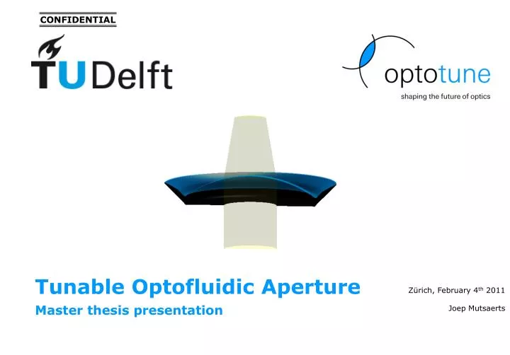
CONFIDENTIAL. Tunable Optofluidic Aperture. Master thesis presentation. Zürich, February 4 th 2011 Joep Mutsaerts. Content. Tunable aperture Concept Trapped liquid Conclusion Membrane model identification Experiments Analysis Simulations. What is a tunable aperture?.

E N D
CONFIDENTIAL Tunable Optofluidic Aperture Master thesis presentation Zürich, February 4th 2011 Joep Mutsaerts
Content • Tunable aperture • Concept • Trapped liquid • Conclusion • Membrane model identification • Experiments • Analysis • Simulations
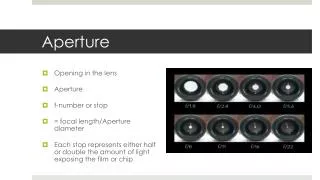
What is a tunable aperture? • Most common: Leaflet structure • Control of: • Light • Depth of Field • Optical quality • F number
What is a tunable aperture? f/32 – slowshutter f/5.6 – fast shutter
Why create a tunable aperture? • Optical quality in mobile phone market • Small size • Low part count • Available design
ML Demonstrator 1 • Trapped fluid problem • Spot depends on speed • Identified possible causes • Particle size • Concentration
ML Demonstrator 2 • Goal: test lower concentration, filtered particles (< 1 μm) • Aperture seems clear, but: • Lens effect caused by remaining fluid • Optical quality depends on speed • Lens effect on aperture edge • Identified possible solution • Surface tension • Coated glass
ML Demonstrator 3 • Goal: Test influence of • Surface tension of water • Glass silicon coating • Trapped fluid problem • High surface tension is not enough • Speed dependent • Identified possible solution • Increase contact angle
ML Demonstrator 4 • Goal: test influence of contact angle • Trapped fluid problem • Soft edge with lens effect
Positive Pressure Test • Air pressurized bulge pushes fluid away. • Particles < 5µm: Clear aperture result but soft edge • Particles > 5µm: trapped fluid problem
Double liquid positive pressure prototype • Optotune lens design with two liquid compartments
Double liquid positive pressure prototype • Prototype results: trapped fluid appears again (speed dependent) • Over time, pigments migrate through membrane into transparent fluid • Particles were not filtered small enough
Feasibility of concept • Use transparent fluid • Is concept pigment dependent?
Aperture: Conclusions and Outlook • Trapped fluid problem has not been solved • Surface profile of transparent lens should be measured • Particle size and concentration play a large role • Lens effect can be solved by double fluid • Bigger and more complicated to produce • Pigments leak through the membrane • Feasibility study advises to put the project on hold • Uncertainty of product quality and costs • Not the lowest hanging fruit
Content • Tunable aperture • Concept • Trapped liquid • Conclusion • Membrane model identification • Experiments • Analysis • Simulations
Membrane model identification Actuation force Pressure Deflection Focal length
Deflection versus pressure - radius 15 14 13 12 d 11 d = 10 mm
Deflection versus pressure - Prestrain 40% 20% 60% 70% 0%
Deflection versus pressure - Thickness 100 μm 200 μm
Measurements statistics • 148 bulge measurements done • Thickness 10 – 200 μm • Radius 5 – 40 mm • Pressure 0 – 30000 Pa
Modelling Isotropic – constant Youngs Non Isotropic – variable Youngs • Further challenges • Bulge loading • Material model might change
Bulge loading • Thickness not constant • Thickness proportional to stretch • Where to measure thickness / stretch?
Stress calculation • ‘Math slide’
Stress strain fit C10 = 210400 Pa C01 = 16005 Pa
CONFIDENTIAL Tunable Optofluidic Aperture Master thesis presentation Zürich, February 4th 2011 Joep Mutsaerts