Download
1 / 15
250 likes | 935 Views
LC Tunable Oscillator. ELG4135 Electronics III Project . Team Members: Hubert Mamba Fu Jingyi Wang Jian. Introduction. Tuned oscillators are largely used in data transmissions and radio communications.

E N D
LC Tunable Oscillator ELG4135 Electronics III Project Team Members: Hubert Mamba Fu Jingyi Wang Jian
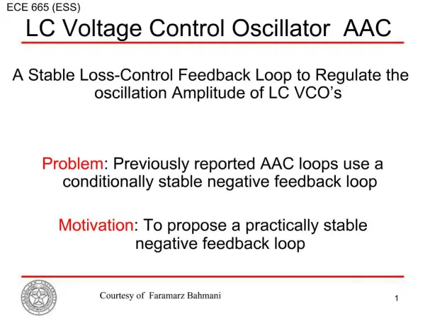
Introduction • Tuned oscillators are largely used in data transmissions and radio communications. • In RF circuits, mainly LC oscillators are used and their frequency is, most of the time, controlled using a variable-capacitance (varicap) diode . This method is a little bit complicated and costly . • We present a single grounded resistance tunable sinusoidal oscillator that • requires only three transistors, some passive components and no variable-capacitance and • the oscillating frequency is controlled through a grounded resistor. Another grounded resistor independently controls the condition of oscillation.
Main Objective: • The main objective of this project is to investigate the performance of the new method (Single grounded resistance tunable Sinusoidal Oscillator). • The usual method (VCO) requires the use of variable-capacitance diode to control the oscillating frequency value. This VCO is expensive and complicated to fabricate. Differential VCO (Collpitt) Oscillator. (from Lucio Carlo Rodoni “http://n.ethz.ch/student/rodonil/da/bericht/node28.html”
Main Objective (cont’d) The alternative (new) method requires no variable-capacitance, it is not expensive and is easy to implement. Its circuit diagram is shown in the figure bellow.
Background Knowledge Review Many people have proposed different models to produce and control Oscillating frequency for different purposes. Bellow is a circuit analysis of a simple LC oscillator. We can see that the oscillating frequency depends on the value of L and C. LC circuit oscillating frequencycalculation:
Circuit analysis result Theoretical calculation: The above formulas are copied from our report.
Theoretical Results The continuous curves are theoretical plot from Matlab The doted curves are got From the Multisim simulation. The simulation on Multisim 8 shows that for k=-1, the oscillating frequency is increasing as R3 increases, and for k=1, the oscillating frequency decreases as R3 decreases, it proves that this single resistor control LC circuit is working. The theoretical result is very close to the simulation ones.
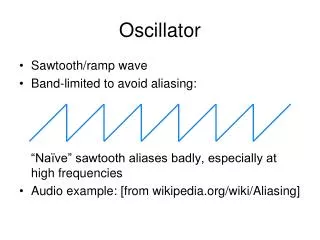
Simulation in Multisim The simulation shows that the circuit can oscillate and the oscillating frequency agrees with the theoretical result. This oscillating simulation plot is at R3=0.56K ohm, and oscillating frequency is 300k Hz at K=1.
Performance of the circuit From the simulation result we can see that the theoretical calculation is very close to the simulation result, especially when R3 is bigger than 40K ohm, the oscillating frequency tends to merge into one value of different k values. It shows that the design of the circuit on this paper is excellent.
Data recorded from the simulation, for each value of R3 and K, we found a corresponding frequency f.
Conclusion • The circuit was tested for positive and negative values of k. • A good quality sinusoidal signal was obtained for the negative value of k, • but the shape of the signal is worse when k is positive, • especially for the low values of R3. • The simulation results are in agreement with the theory, particularly for negative values of k.
Things to be improved • It is not easy to get higher frequency values (Giga hurts) as we would in practice. • The transformer ferromagnetic losses, the lag phase brought by Q1, Q2 and Q3, the output impedance of Q3 and the stray capacity in parallel with R1//R2 limit this high frequency value. • Designing more powerful amplitude limitation device, based on nonlinear voltage-controlled voltage source • Further research to increase the quality factor (by decreasing the value of resistors R1 and R2) should allow the • improvement of the signal shape for the positive values of k. • Higher frequency values should also be obtained.
References • J. Bayard ‘ Single grounded resistance tunable sinusoidal oscillator’, IEEE Proc.-Circuits Devices Syst., Vol 151,No.2,April 2004. • Chen, JJ., Chen, C.C., Tsao, H.W., and Liu, S.I. :’Current mode oscillators using single current follower’, Electron Lett., 1991,27,(22), pp.2056-2059 • Tao, Y., and Fidler, J.K.:’ Electronically tunable dual OTA second order sinusoidal oscillators/filters with non-interacting controls: a systematic synthesis approach’, IEEE Trans. Circuits Syst. I, Fundam, Theory AppL, 2000,47,(2), pp.117-129 • Cam,U., Kuntman, H. ,and Acar, C. :’On the realization of OTA-C oscillators’,Int.J.Electron,1998,84,(3),pp.313-326
Special Words Special thanks to the Prof. Dr. Habbash And The teaching assistants