Download

1 / 15
150 likes | 304 Views
CPE 400 / 600 Computer Communication Networks. Lecture 20. Chapter 5 Link Layer. slides are modified from J. Kurose & K. Ross. Our goals: understand principles behind data link layer services: error detection, correction sharing a broadcast channel: multiple access link layer addressing

E N D
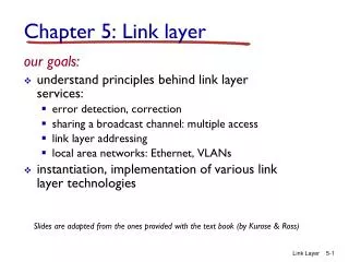
CPE 400 / 600Computer Communication Networks Lecture 20 Chapter 5Link Layer slides are modified from J. Kurose & K. Ross
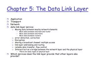
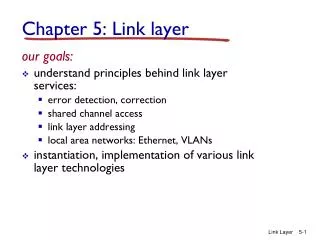
Our goals: understand principles behind data link layer services: error detection, correction sharing a broadcast channel: multiple access link layer addressing reliable data transfer, flow control: done! instantiation and implementation of various link layer technologies Chapter 5: The Data Link Layer DataLink Layer
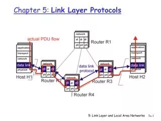
Some terminology: hosts and routers are nodes communication channels that connect adjacent nodes along communication path are links wired links wireless links LANs layer-2 packet is a frame,encapsulates datagram Link Layer: Introduction data-link layer has responsibility of transferring datagram from one node to adjacent node over a link DataLink Layer
datagram transferred by different link protocols over different links: e.g., Ethernet on first link, frame relay on intermediate links, 802.11 on last link each link protocol provides different services e.g., may or may not provide rdt over link transportation analogy trip from Princeton to Lausanne limo: Princeton to JFK plane: JFK to Geneva train: Geneva to Lausanne tourist = datagram transport segment = communication link transportation mode = link layer protocol travel agent = routing algorithm Link layer: context DataLink Layer
Link Layer Services • framing, link access: • encapsulate datagram into frame, adding header, trailer • channel access if shared medium • “MAC” addresses used in frame headers to identify source, dest • different from IP address! • reliable delivery between adjacent nodes • we learned how to do this already! • seldom used on low bit-error link (fiber, some twisted pair) • wireless links: high error rates • Q: why both link-level and end-end reliability? • flow control: • pacing between adjacent sending and receiving nodes DataLink Layer
Link Layer Services (more) • error detection: • errors caused by signal attenuation, noise. • receiver detects presence of errors: • signals sender for retransmission or drops frame • error correction: • receiver identifies and corrects bit error(s) without resorting to retransmission • half-duplex and full-duplex • with half duplex, nodes at both ends of link can transmit, but not at same time DataLink Layer
in each and every host link layer implemented in “adaptor” (aka network interface card NIC) Ethernet card, PCMCI card, 802.11 card implements link, physical layer attaches into host’s system buses combination of hardware, software, firmware application transport network link link physical Where is the link layer implemented? host schematic cpu memory host bus (e.g., PCI) controller physical transmission network adapter card DataLink Layer
sending side: encapsulates datagram in frame adds error checking bits, rdt, flow control, etc. receiving side looks for errors, rdt, flow control, etc extracts datagram, passes to upper layer at receiving side Adaptors Communicating datagram datagram controller controller receiving host sending host datagram frame DataLink Layer
5.1 Introduction and services 5.2 Error detection and correction Lecture 20: Outline DataLink Layer
Error Detection • EDC= Error Detection and Correction bits (redundancy) • D = Data protected by error checking, may include header fields • Error detection not 100% reliable! • protocol may miss some errors, but rarely • larger EDC field yields better detection and correction otherwise DataLink Layer
Parity Checking Two Dimensional Bit Parity: Detect and correct single bit errors Single Bit Parity: Detect single bit errors 0 0 DataLink Layer
Internet checksum (review) Goal: detect “errors” (e.g., flipped bits) in transmitted packet (note: used at transport layer only) Sender: • treat segment contents as sequence of 16-bit integers • checksum: addition (1’s complement sum) of segment contents • sender puts checksum value into UDP checksum field Receiver: • compute checksum of received segment • check if computed checksum equals checksum field value: • NO - error detected • YES - no error detected. But maybe errors nonetheless? DataLink Layer
Checksumming: Cyclic Redundancy Check • view data bits, D, as a binary number • choose r+1 bit pattern (generator), G • goal: choose r CRC bits, R, such that • <D,R> exactly divisible by G (modulo 2) • receiver knows G, divides <D,R> by G. If non-zero remainder: error detected! • can detect all burst errors less than r+1 bits • widely used in practice (Ethernet, 802.11 WiFi, ATM) DataLink Layer
CRC Example Want: D.2r XOR R = nG equivalently: D.2r = nG XOR R equivalently: if we divide D.2r by G, want remainder R D.2r G R = remainder[ ] DataLink Layer
Introduction and services Link layer Services Error detection and correction Parity check Checksum CRC Lecture 20: Summary DataLink Layer