Download
1 / 21
210 likes | 222 Views
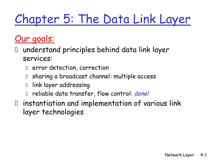
Our goals: understand principles behind data link layer services: error detection, correction sharing a broadcast channel: multiple access link layer addressing reliable data transfer, flow control: done! instantiation and implementation of various link layer technologies.

E N D
Our goals: understand principles behind data link layer services: error detection, correction sharing a broadcast channel: multiple access link layer addressing reliable data transfer, flow control: done! instantiation and implementation of various link layer technologies Chapter 5: The Data Link Layer Network Layer
5.1 Introduction and services 5.2 Error detection and correction 5.3Multiple access protocols 5.4 Link-layer Addressing 5.5 Ethernet 5.6 Link-layer switches 5.7 PPP 5.8 Link virtualization: ATM, MPLS Link Layer Network Layer
Link Layer Services • framing, link access: • encapsulate datagram into frame, adding header, trailer • channel access if shared medium • “MAC” addresses used in frame headers to identify source, dest • different from IP address! Network Layer
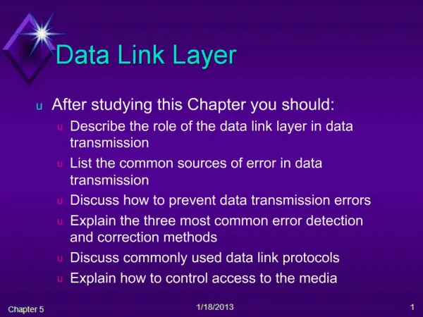
Link Layer Services (more) • error detection: • errors caused by signal attenuation, noise. • receiver detects presence of errors: • signals sender for retransmission or drops frame • error correction: • receiver identifies and corrects bit error(s) without resorting to retransmission Network Layer
Data link: usual approach • Usual approach • Data link • breaks the bit stream up into discrete frames • computes the checksum for each frame • This checksum is recomputed at the destination • Breaking bit stream up • Character count • Flag bytes with byte stuffing • Starting and ending flags with bit stuffing Network Layer
Framing • First method • Uses a field in the header specifying # characters • Trouble • Count can be garbled by a transmission error Network Layer
Framing (cont’d) • Starting and ending delimiters • => flag bytes • Flag byte pattern occurring in the data • => byte stuffing Network Layer
If an escape byte occurs in the middle of the data • A framing flag byte can be • Distinguished from one in the data • By the absence or presence of an escape byte before it • If an escape byte occurs in data • It is stuffed with an escape byte • Example of byte sequences after stuffing • Single escape byte => part of an escape sequence • Double one => a single escape occurred in the data • In all cases, delivered byte sequence same as original Network Layer
Bit stuffing • Frame begins and ends with 01111110 • If sender encounters 5 consecutive 1s • Sender stuffs a 0 bit into the outgoing bit stream • Receiver destuffs the 0 bit Network Layer
5.1 Introduction and services 5.2 Error detection and correction 5.3Multiple access protocols 5.4 Link-layer Addressing 5.5 Ethernet 5.6 Link-layer switches 5.7 PPP 5.8 Link Virtualization: ATM. MPLS Link Layer Network Layer
Error detection and correction • Transmission errors are common on local loops • transmission errors are going to be with us for years • => need for error correcting or detecting codes • Error correcting codes • include enough redundant information along with block of data • To enable receiver to deduce what transmitted data was • Suitable for channels that make many errors • Error detecting codes • include only enough redundancy to allow • Receiver to deduce that an error occurred, not which error • Suitable for highly reliable channels Network Layer
Error correcting and detecting codes: terminology • A frame consists of m data bits • And r redundant, or check, bits • => total length n = m + r • The n bit (data + check bits) => n-bit codeword • Hamming distance • The # bit positions in which 2 codewords differ • Example: given 1001001 and 10110001, • 3 bits differ => hamming distance = 3 Network Layer
Error correcting and detecting code: rules • To detect d errors, you need a distance d+1 code • Example: code in which single parity bit is appended • The parity bit is chosen so that # of 1 bits is even (or odd) • A code with single parity bit has a distance 2 • => it can be used to detect single errors • To correct d errors, you need a distance 2d+1 code • Example: 0000000000, 0000011111, 1111100000 • This code has a distance 5 => can correct double errors • If 0000000111 arrives => original must have been 0000011111 Network Layer
Lower limit on the number of check bits • We want to design a code • with m message bits and r check bits • Allowing all single errors to be corrected • This requirement becomes • This put a lower limit on the number of check bits • Needed to correct a single error Network Layer
Error correcting code: Hamming code • A data bit in position k • is checked by just those check bits occurring in its expansion Network Layer
Use of Hamming code to correct burst errors Network Layer
Error detecting codes • Cyclic Redundancy Check (CRC) • is in widespread use, and called polynomial code • treats bits as 0 and 1 coefficients of polynomials • For example: 110001 represents x5 +x4 + x0 • Sender and receiver agree • upon a generator polynomial G(x) • To compute the checksum for some frame of m bits M(x) • => append a checksum to the end of frame • such that polynomial is divisible by G(x) • Receiver divides check-summed frame by G(x) • If there is a remainder => there has been an error Network Layer
Checksumming: Cyclic Redundancy Check • view data bits, D, as a binary number • choose r+1 bit pattern (generator), G • goal: choose r CRC bits, R, such that • <D,R> exactly divisible by G (modulo 2) • receiver knows G, divides <D,R> by G. If non-zero remainder: error detected! • can detect all burst errors less than r+1 bits • widely used in practice (Ethernet, 802.11 WiFi, ATM) Network Layer
Algorithm for computing the checksum • Let r be the degree of G(x) • Append r zeros to the low-order end of the frame • => xr M(x) • Divide the bit string corresponding to G(x) • Into the bit string corresponding xr M(x) using • Modulo 2 division • Subtract the remainder from xr M(x) • The result is the checksumed frame to be transmitted Network Layer
Error detecting codes: example Calculation of the polynomial code checksum. Network Layer
CRC Example Want: D.2r XOR R = nG equivalently: D.2r = nG XOR R equivalently: if we divide D.2r by G, want remainder R D.2r G R = remainder[ ] Network Layer