Download
1 / 13
180 likes | 363 Views
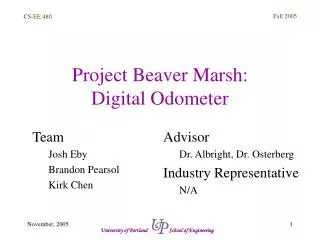
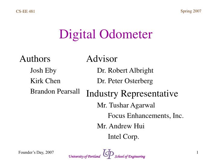
Digital Odometer. Advisor Dr. Robert Albright Dr. Peter Osterberg Industry Representative Mr. Tushar Agarwal Focus Enhancements, Inc. Mr. Andrew Hui Intel Corp. Authors Josh Eby Kirk Chen Brandon Pearsall. Agenda. Introduction Josh Eby Background Josh Eby Methods Kirk Chen

E N D
Digital Odometer • Advisor • Dr. Robert Albright • Dr. Peter Osterberg • Industry Representative • Mr. Tushar Agarwal • Focus Enhancements, Inc. • Mr. Andrew Hui • Intel Corp. Authors Josh Eby Kirk Chen Brandon Pearsall University of Portland School of Engineering
Agenda • Introduction Josh Eby • Background Josh Eby • Methods Kirk Chen • Results Kirk Chen • Conclusions Brandon Pearsall • Demonstration Brandon Pearsall University of Portland School of Engineering
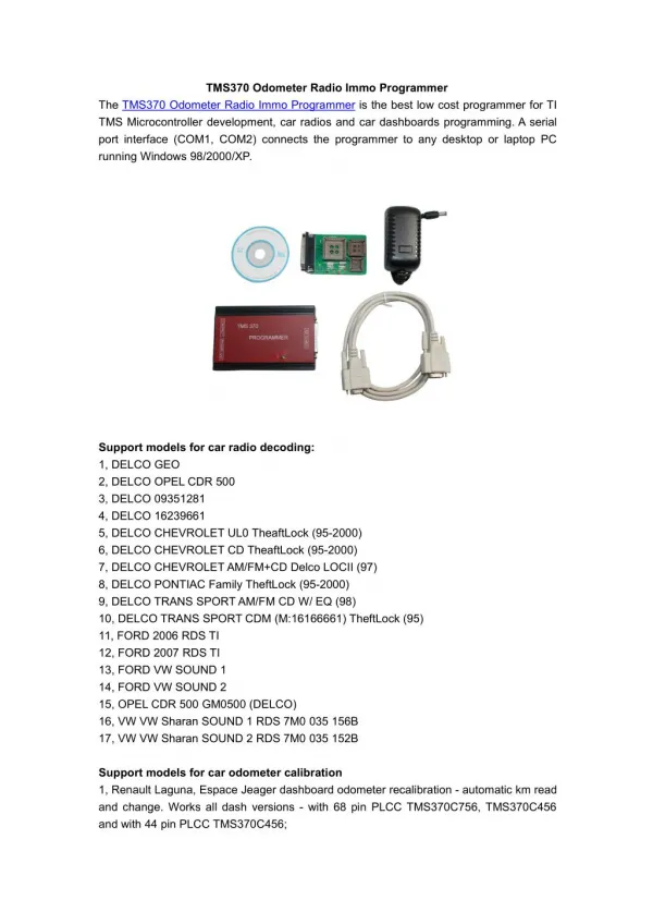
Introduction • Digital Odometer using CMOS technology. • Tracks the distance that a rotating wheel has moved and displays it on 7-segment LCDs. • CMOS technology simplifies a problem. • Integration techniques between different technologies. University of Portland School of Engineering
Background • Digital Odometer vs. Mechanical Odometer. • Analog vs. Digital signals. • Signal Integrity. • CMOS chip & Photo-Reflective Sensor. University of Portland School of Engineering
Methods • Functional Blocks. -Platform with Motor & Wheel. -Sensor & Output Conditioning. -Counting Circuit. -Decoder/Power Relay/Display. University of Portland School of Engineering
Results • Rotating Wheel – Sensor – Signal Conditioning – CMOS chip – Display. • Top-down, Bottom-up Implementation. University of Portland School of Engineering
DC Power Supply (120V AC) Rotating Wheel with Reflector Electric Motor Stationary Sensor Signal Conditioner CMOS Counter 7-Segment Decoders Power Relay and Display C1 C2 C3 C4 Results Block Diagram University of Portland School of Engineering
Results Final Circuit University of Portland School of Engineering
Conclusions • Digital Odometer Prototype. • Combining and Integrating Various Technologies. • Limited by Speed of Wheel. - Better Sensor. - Shorter Hold Time on Debouncer. • Limited to One Size of Wheel. - Additional Counters & Microprocessors. University of Portland School of Engineering
Demonstration • Digital Odometer. • 7-Segment Displays. • Counts Distance/Rotations Traveled. • Synchronous Reset. University of Portland School of Engineering
Demonstration Optical Sensor Electric Motor LED Display MOSIS Chip & Circuit Housing Conceptual Design Wheel University of Portland School of Engineering
Demonstration Final Prototype University of Portland School of Engineering
Thank You. Are there any questions? University of Portland School of Engineering