Download
1 / 28
280 likes | 432 Views
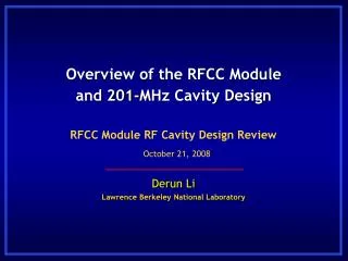
Derun Li Lawrence Berkeley National Laboratory. MICE RFCC Module. MICE Schedule Review RAL, UK May 24, 2011. Outline. Overview of MICE RFCC module RF cavities and superconducting coupling coil magnets Current status of the RFCC module Plan and schedule Success oriented schedule

E N D
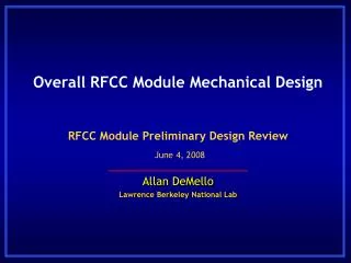
Derun Li Lawrence Berkeley National Laboratory MICE RFCC Module MICE Schedule Review RAL, UK May 24, 2011
Outline • Overview of MICE RFCC module • RF cavities and superconducting coupling coil magnets • Current status of the RFCC module • Plan and schedule • Success oriented schedule • Concerns and risks • Summary
Overview of MICE RFCC Module RFCC module Two RFCC (RF cavity and superconducting Coupling Coil magnet) modules in MICE cooling channel: compensate for muon longitudinal energy losses in AFC
Overview of MICE RFCC Module (cont’d) SC CC magnet 201-MHz cavities Each RFCC module has four 201-MHz NC RF cavities and one SC coupling coil (solenoid) magnet; each RF cavity has a pair of curved Be windows and coaxial loop couplers
The RFCC Module: RF Cavities • Four normal conducting 201-MHz RF cavities mounted in a vacuum vessel • Cavity is formed by e-beam welding from two spun half shells; • Large beam iris (21-cm radius) terminated by thin and curved beryllium windows (no differential pressure on the windows); • Four ports oneach cavity: two coaxial loop couplers with integrated ceramic windows; one vacuum port; one view and diagnostic port; • Six evenly spaced tuners on cavity equator; • Water cooling pipes brazed to cavity body; • EP of the cavity inner surface; • Support structure.
The RFCC Module: SC CC Magnet • Design and fabrication in collaboration with Harbin Institute of Technology (HIT) and Shanghai Institute of Applied Physics (SINAP), fabrication contract awarded to QiHuan Company in Beijing, China • Onesuperconducting coupling coil (solenoid) magnet around the four RF cavities: • Largest magnets in MICE: • Diameter 1.5 m and 281-mm of coil length; • Stored energy 13 MJ; • 250 A (design value), 166 turns/layer and 96 layers; • Three cryocoolers (baseline) to cool the magnet at 4.2 K; • Quench protection: passive with cold diodes and resistors; • Self-centering support system of the cold-mass; • Superconductors: 1 mm by 1.65 mm ( 87 km/coil).
Current Status of RFCC Module • RF cavities: • All ten cavities (two spares) received at LBNL and five measured; • Received and accepted nine beryllium windows; • Ten ceramic RF windows ordered and received ( 4 at LBNL and 6 at UM); • Six full size tuner flexures are being fabricated at UM and LBNL; • Components for 6 actuators are to be fabricated at UM; • Cavity post-processing (surface cleaning and preparation for EP) to start this year at LBNL; • The single cavity vacuum vessel drawings are complete and sent to Fermilab, and fabrication will start. • SC CC magnets: • 1st coil winding complete at QiHuan Company; • Cover plate of cold-mass and LHe pipe starts at HIT in early June 2011; • Cryostat design complete; • Plans for cold-mass and cryostat testing are being developed.
All Ten RF Cavities (Two Spares) at LBNL One cavity on inspection stand Fabrication set-up cavity Six cavities in their shipping crates; three cavities are stored in another location
RF Cavity Electro-polish at LBNL • The inner surface of each cavity will be electro-polished at LBNLusing the techniques developed at JLab for the prototype cavity at MTA, Fermilab; • EP setup and testing starts Oct. this year.
RF Cavity Frequency Tuner Components • Dual – action actuator • Flexure • tuner arm • RF cavity
RF Cavity Frequency Tuner Flexure • Six tuner flexures are being fabricated at the University of Mississippi, the first one arrived LBNL last week for inspection, final fabrication finish at LBNL.
Actuator Component Fabrication Upper piston Center plate Lower piston Lower support • Actuator mechanical components (except bellows) for 6 actuators to be fabricated at UM, but may have to be done at LBNL due to machining limitation at UM.
Actuator Bellows and Tuner Control System • Old bellows • New bellows • Sample bellows from a new vendor is • at LBNL for testing; • Emerson ER3000 electronic pressure controllers have been tested at LBNL • PierrickHanlet (Fermilab/IIT) visited LBNL and received the controllers for control software development.
Toshiba Ceramic RF Windows • An integral part of RF power (loop) coupler; • Ten Toshiba ceramic RF windows ordered by UM delivered to us (four at LBNL for inspection now, six at UM now).
Beryllium Windows • Curved Beryllium windows: • 0.38 mm in thickness and • 21 cm in radius • Eleven Beryllium windows have been fabricated; • Nineare Ti-N coated and accepted; • Six of eleven windows have been evaluated/measured; • Visited BW last week: two windows were rejected due to excessive distortion • Two more will be re-made with proposed/improved technique.
Evaluation of the Beryllium Windows • Plot of the laser inspection machine data Distorted window • Constant radius scan • Accepted • Rejected
RF Power (loop) Coupler • Testing/experience of the prototype cavity at MTA: sparking at the coupler • MICE RF power coupler design is complete and ready for fabrication; • The coupler design has an increased gap spacing; • The sparking region can be Ti-N coated if necessary • (will be tested at MTA using the prototype cavity); • Adding diagnostics: arc detector at the coupler • region.
RF Cavity Future Work • Physical and frequency measurements will be performed on the remaining 5 cavities; • Electro-polish of the inside surface of each cavity remains to be done at LBNL; • The cavities must be “tuned” to each other for best center frequency (10 cavities) by plastic deformation after completion of RF measurement of all 10 cavities; • Final design and drawings of RF power coupler; • Single cavity vessel fabrication and testing at MTA, Fermilab.
Status of SC Coupling Coil Magnet • 1st coil winding complete; cover plate and LHe pipe welding next month; • Cryostat design complete, review process started: • Three cryocoolers (baseline); • Improved cooling circuit design; • 40-mm more spacing for MLI insulation and assembly. Cold-mass Cryostat RFCC module
1st CC Coil Winding 1st coil winding complete in Dec. 2010 SC wire loop for connecting to QP diodes. SC wire leads from cold-mass. Coil winding at QiHuan: last layer of SC wire (left) and finished Al banding (right)
Status of the CC Cryostat Design • Design complete by SINAP and sent to LBNL at end of March 2011; • Procurement of Solid-Edge software at LBNL: • Translation and updating of the 3D model received from SINAP complete; • Implementation of updated design/changes starts soon. • 261 2-D drawings sent out to RAL, Fermilab and RAL for reviewing; • Further design improvement is implemented at LBNL this month by Drs. Li Wang (SINAP) and TapioNiinikoski: • Review fabrication and assembly procedures; • Improved cooling circuit design for easier assembly and MLI wrapping; • Identified and finalized diagnostic sensors (location and types); • Improved designs of HTS leads and SC leads for better thermal and mechanical stabilizations; • Quench protection to be re-evaluated at LBNL or by others; • Cold-mass and cryostat testing plan is being explored.
The Cooling Circuit Design • Simplified design of the cooling circuit for easy assembly: • Moving clamps and joints underneath the copper plate + flexible pipe; • Addition of a copper sheet for easier MLI wrapping; • Better thermal and mechanical stabilizations of HTS leads.
The Cryostat Design • Kenol connector of LHe fill-line inside cooling pipe for easy assembly; • The LHe fill-line goes to the bottom reservoir. • New upper and bottom reservoir designs; • Welding procedures allow for cold-mass test without the need of the certification of pressure vessel; • A diffuser in bottom reservoir to prevent vapor • trapping.
CC Magnet Future Work • Final machining of cold-mass cover plate and pipe bending at QiHuan to be completed by end of May and shipping to HIT early June 2011; • Welding fixture complete this week at HIT, welding of cold-mass cover plate and LHe pipes at HIT starts mid-June 2011; • Finished cold-mass to be shipped to LBNL at end of August 2011; • Vacuum impregnation of epoxy at LBNL. • Cold-mass testing plan is being explored: • Cold-mass testing in the US, potential places: Fermilab or MIT; • Identified a cryostat at FSU. • Cryostat fabrication and assembly review summer (August) of 2011; • Fabrication of the cryostat parts starts after the review. • Quench protection re-evaluation starts at LBNL soon, and possible assistance from MIT group; • The ¼ testing coil testing preparation is underway and will be tested at HIT this year (assembly contract awarded to a local company);
Plan and Schedule • RFCC module schedule is mainly determined by the schedule of CC magnets; • RF cavity work is in good shape and currently on-hold to save resources for SS (highest priority) and CC magnets; • Cold-mass testing of the first coil is critical, • ¼ testing coil at HIT; • Cold-mass testing in the US, potentially at Fermilab or MIT, best estimate will be September to October 2011. • 2nd and 3rd coil winding starts after successful testing of the 1st coil; • Each coil winding takes 3-4 month at QiHuan. • Fabrication of cryostat parts starts summer 2011 (after review); • CC magnet testing with the real cryostat if the 1st coil testing is successful • Fabrication (in China) and assembly (US); • Final QP system, design and assembly; • Transfer techniques, namely cryostat welding, assembly and testing to QiHuan Company for fabrication of the 2nd and 3rd magnets in China.
CC Magnet Schedule (Best Estimate) • First CC magnet (MUCOOL): • Complete fabrication of the 1st Cold-mass in China: August 2011; • Cold-mass testing in the US: starts Sept-October 2011; • Cryostat and institute (?) • A meeting in early June at Fermilab to discuss the cold-mass testing by MAP PMG • Fabrication of cryostat parts: Sept-Nov. 2011; • CC magnet QP study starts July 2011; • Cryostat assembly and magnet testing: Jan-March 2012; • 2nd and 3rd CC magnets (MICE): • 2nd Cold-mass fabrication (coil winding and assembly): • Dec. 2011 – March 2012; 3rd cold-mass: March 2012 – June 2012; • Cryostat fabrication and assembly (#2 and #3): March 2012 – Sept.2012; • Magnet testing (?): where and when?
Concerns and Risks • Cold-mass testing and cryostat assembly: • Resources: funding and qualified personnel: • Hard to schedule without finding the right cryostat and where the testing can be conducted (qualified groups); • Quench protection scheme (LBNL, Fermilab and MIT); • Cryostat fabrication (China), assembly and magnet testing (which US group?). • 2nd and 3rd CC magnets rely on experience and techniques developed from the 1st magnet: • Must succeed in the 1st magnet; • Transfer of technology (assembly and testing) to QiHuan Company; • Supervision of 2nd and 3rd magnet fabrication and assembly by qualified personnel.
Summary • RF cavities, post processing and associated accessory components are under control at LBNL • RF work schedule dictated by the cc magnets and available funding • The CC magnet design has been improved significantly in the past year, we are more confident the design • Experience and lessons learned from SS magnets; • Help from cryogenics and magnet experts, and from MICE and MAP collaboration; • Progress on cryostat design and fabrication of the 1st cold-mass; • Schedule developed based on what we know so far. • The 1st cold-mass testing plan is being developed; • Realistic schedule of RFCC fabrication will/can be developed after testing of the 1st CC magnet.