Download
1 / 44
440 likes | 672 Views
Progress on the MICE RFCC Module . Mike Zisman/Steve Virostek Lawrence Berkeley National Laboratory. MuCool Test Area RF Workshop October 15, 2008. Progress Summary. The MICE cavity design is heavily based on the successful MuCool 201-MHz prototype RF cavity and lessons learned

E N D
Progress on the MICE RFCC Module Mike Zisman/Steve Virostek Lawrence Berkeley National Laboratory MuCool Test Area RF Workshop October 15, 2008
Progress Summary • The MICE cavity design is heavily based on the successful MuCool 201-MHz prototype RF cavity and lessons learned • Fabrication and post processing • Cavity conditioning and operation • Engineering design of the cavity is complete • CAD model of the cavity, tuners, support and vacuum • Fabrication schemes and vendor identification • RFCC module engineering design nearing completion • Possible operation at LN temperature? • Design accommodates LN operation, but is very challenging Zisman/Virostek - LBNL - October 15, 2008
Muon Ionization Cooling Experiment RFCC RFCC Spectrometer Solenoid 1 AFC AFC Spectrometer Solenoid 2 Absorber and Focusing Coil (AFC) Zisman/Virostek - LBNL - October 15, 2008
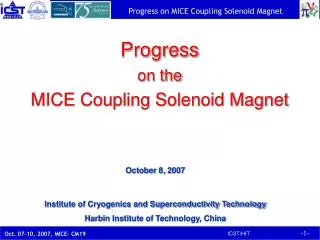
SC coupling Coil Curved Be window Cavity Couplers Vacuum Pump 201-MHz cavity 2 RFCC Modules, 8 Cavities Zisman/Virostek - LBNL - October 15, 2008
RF Cavity Summary • Fabrication of the prototype cavity was successful • A slight reduction in cavity diameter to raise the frequency has been specified and analyzed • The fabrication techniques used to produce the prototype will be used to fabricate the MICE RF cavities • A detailed WBS schedule for the design and fabrication of the MICE RF cavities has been developed Zisman/Virostek - LBNL - October 15, 2008
Cavity Design Parameters • Cavity design parameters: • Frequency: 201.25 MHz • β = 0.87 • Shunt impedance (VT2/P): ~ 22 MΩ/m • Quality factor (Q0): ~ 53,500 • Be window diameter and thickness: 42-cm and 0.38-mm • Nominal parameters for MICE and cooling channels in a neutrino factory: • 8 MV/m(~16 MV/m)peak accelerating field • Peak input RF power:1 MW(~4.6 MW)per cavity • Average power dissipation per cavity:1 kW(~8.4 kW) • Average power dissipation per Be window:12 watts(~100 watts) Zisman/Virostek - LBNL - October 15, 2008
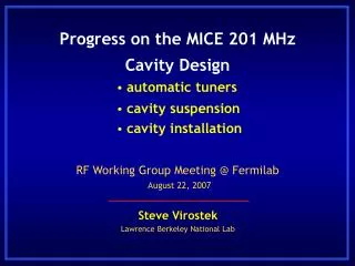
Recent Progress: RF Cavity Design • 3-D Microwave Studio RF parameterized model with ports and curved Be windows • Hard to reach the design frequency by spinning • Frequencies between cavities should be able to achieve within 100 kHz • Approaches • Modification the spinning form • Targeting for higher frequency • Fixed tuner to tune cavity close to design frequency (deformation of cavity body) • Tuners are in push-in mode lower frequency Zisman/Virostek - LBNL - October 15, 2008
Numerical Study with B Field • Preliminary studies, in collaboration with colleagues at SLAC using Omega-3P and Track-3P codes • Cavity with flat windows:5 MV/mon axis;2-Tuniform external magnetic field; scan of a few points from one cavity side Trajectories with external B = 2-T field Trajectories without external B field E field contour Zisman/Virostek - LBNL - October 15, 2008
High Power RF Tests on Prototype Cavity • The cavity was first tested with flat copper windows and reached ~ 16 MV/m quickly and quietly • The cavity then was tested with thin and curved Be windows and again reached to ~19 MV/m quickly • Cavity frequency had to be retuned • Cavity frequency wasstable during the operation, however, we did observe frequency shift due to RF heating on the windows • Frequency shift of ~ 125 kHz (from 0 to ~ 19 MV/m, 150-micro-second pulse, 10-Hz repetition rate) in ~ 10 minutes, well within the tuning range (230 kHz/mm per side, 2-mm range) • With a few hundred Gauss stray field from Lab-G magnet, the cavity gradient can be maintained at 19 MV/m • To test with stronger external magnetic fields • Move the cavity closer to Lab-G magnet • SC coupling coil for MuCool Zisman/Virostek - LBNL - October 15, 2008
Lab-G magnet The 201-MHz cavity Tests with Stronger Magnetic Fields • New vacuum pumping system • Separation of the nearest curved Be window from the face of Lab-G magnet is 10-cm (before was 110-cm) • Maximum magnetic field near the Be window 1.5 Tesla (at 5 Tesla in magnet) • Test Results: • Multipactoring was observed over the entire magnetic field range up to 1.1-T at nearest Be window • A strong correlation exists between cavity vacuum and radiation levels • We have achieved ~ 14 MV/m at 0.75-T to the nearest curved thin Be window • Recent test results show plateau at ~10 MV/m Zisman/Virostek - LBNL - October 15, 2008
RF Cavity Assembly Zisman/Virostek - LBNL - October 15, 2008
RF Cavity Fabrication Overview The same fabrication techniques used to make the prototype cavity will be used for the MICE RF cavities Engineering CAD Model of the RF Cavity • Cavity half-shells to be formed by metal spinning • Precision milling of large parts (1.2 m diameter) • Precision turning of mid-sized parts (0.6 m dia.) • Precision manufacture of smaller parts • CMM measurements throughout the process • To limit any annealing and maintain cavity strength, e-beam welding will be used for all cavity welding • cavity equator, stiffener rings, nose rings, port annealing and port flanges • Cavity inside surfaces are finished by electro-polishing Prototype RF Cavity Zisman/Virostek - LBNL - October 15, 2008
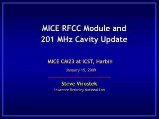
Recent Progress • RFCC engineering CAD model refined • RF and engineering design of 201-MHz RF cavity complete • Integration and interface issues addressed • Vendor identification and qualification near complete Zisman/Virostek - LBNL - October 15, 2008
Recent Progress (procurement & fab) • The large copper sheets used in the fabrication of the cavity shells have been ordered and will arrive at LBNL in mid-December • A series of vendor qualification visits has been conducted • Applied Fusion - San Leandro, CA (e-beam welding, machining) • Meyer Tool & Mfg., Inc. - Chicago, IL (machining) • Sciaky, Inc. - Chicago, IL (e-beam welding) • Roark Welding & Engineering - Indianapolis, IN (e-beam welding, machining) • ACME Metal Spinning – Minneapolis, MN (cavity shell spinning) • Other vendors have been identified • Midwest Metal Spinning, Inc. –Bedford, IN (cavity shell spinning) Zisman/Virostek - LBNL - October 15, 2008
Other Module Components • Beryllium window design is complete; windows are in the process of being ordered (8 per module needed) • Design and analysis of the cavity frequency tuners is complete, drawings to be done soon • A hexapod cavity suspension system has been incorporated in the design • The RF coupler will be based on the SNS design using the off the shelf Toshiba RF window • The vacuum system includes an annular feature coupling the inside and the outside of the cavity (further analysis of vacuum rupture scenarios TBD) Zisman/Virostek - LBNL - October 15, 2008
Other Module Components Cavity Suspension Dynamic Tuners RF Coupler Beryllium Window Vacuum System Zisman/Virostek - LBNL - October 15, 2008
201 MHz Beryllium Windows • Each cavity has two Be windows • 42-cm diameter and 0.38-mm thick • Window is formed at high temperature and later brazed to copper frames • Thin TiN coatings on both sides of the window • One window curves into the cavity and one curves out • Already tested up to 5 MW in 201-MHz cavity at MTA, FNAL 42-cm Zisman/Virostek - LBNL - October 15, 2008
Cavity Tuner Design Features • Six tuners spaced evenly around each cavity provide individual frequency adjustment through a feedback loop • Layout is offset by 15º from vertical to avoid conflict with cavity ports • Tuners touch cavity and apply loads only at the stiffener rings • Tuners operate in “push” mode only (i.e. squeezing) Zisman/Virostek - LBNL - October 15, 2008
Tuner component Details Actuator & bellows assembly Fixed arm Pivoting arm Forces are transmitted to the stiffener ring by means of “push” loads applied to the tuner lever arms by the actuator assembly Zisman/Virostek - LBNL - October 15, 2008
Hexapod Strut Arrangement • Analysis of a hexapod strut system is complete • Each cavity will contain a dedicated set of 6 suspension struts arranged in a hexapod type formation • This system spreads the gravity load of the cavity across several struts Example of a hexapod stage Zisman/Virostek - LBNL - October 15, 2008
Hexapod Strut Cavity Mounting • Copper mounting block will be e-beam welded directly to the RF cavity • The cavity has very little deformation at the mounting block location Zisman/Virostek - LBNL - October 15, 2008
Vacuum System NEG (non-evaporable getter) pump Cross sectional view of vacuum system • A NEG pump has been chosen because it will be unaffected by the large magnetic field • A vacuum path between the inside and outside of the cavity eliminates the risk of high pressure differentials and the possible rupture of the thin beryllium window Zisman/Virostek - LBNL - October 15, 2008
Vacuum Vessel and Support Summary • Engineering 3D CAD model of the vacuum vessel mechanical design is complete • Standard machining and manufacturing methods will be used • A plan for attaching the coupling coil and the vacuum vessel together has been developed • Conceptual design of the support stand is complete (analysis will need to be performed) • A method for assembling the cavities into the vacuum vessel has been formulated • A conceptual design of the cavity water cooling feedthrough system is finished Zisman/Virostek - LBNL - October 15, 2008
Vacuum Vessel Fabrication • Vacuum vessel material must be non-magnetic and strong therefore 304 stainless steel will be used throughout • The vacuum vessel will be fabricated by rolling stainless steel sheets into cylinders • Two identical vessel halves will be fabricated with all ports and feedthroughs Main 1400mm rolled tube Bellows flange Smaller diameter rolled tube Zisman/Virostek - LBNL - October 15, 2008
Vacuum Vessel and Coupling Coil Zisman/Virostek - LBNL - October 15, 2008
Vacuum Vessel/Coupling Coil Integration • LBNL will weld in gussets that fit between the coupling coil and the vacuum vessel • Sixteen special gussets are welded between the coupling coil magnet’s cold mass support tubes and the magnet housing • The gussets will transfer the magnetic loads between the coupling coil and the vacuum vessel Zisman/Virostek - LBNL - October 15, 2008
RFCC Attachment to Support Stand • The vacuum vessel is bolted to a saddle made up of small plates welded to the support stand • Stainless steel bars are welded onto the vacuum vessel for attaching bolted gusset plates Bolted gusset mounting bars Zisman/Virostek - LBNL - October 15, 2008
RFCC Support Stand • RFCC support stand must withstand a longitudinal force of 50 tons transferred from the coupling coil • Bolted gussets and cross bracing provide shear strength in the axial direction (analysis will confirm the stand design) Zisman/Virostek - LBNL - October 15, 2008
Liquid Nitrogen Cooling Considerations • Suspension of cavities on struts provides low heat leak from cavity to vacuum vessel • Beryllium window FEA thermal analysis will need to be performed with new parameters • The cavity frequency will be shifted (approximately 600 kHz), therefore tuning system or RF power source modifications will be needed • Insulators will need to be added to the RF couplers • Coaxial LN feedthrough tubes will be needed to insulate the connection outside of vacuum MICE RF Cavity – Mechanical Design and Analysis Zisman/Virostek - LBNL - October 15, 2008 Allan DeMello - Lawrence Berkeley National Lab - June 4, 2008 Page 29
Module Assembly Sequence Beryllium windows are installed onto the cavities Bare cavity Zisman/Virostek - LBNL - October 15, 2008
Module Assembly Sequence Assembly of the tuners onto the cavities (w/o actuators) Install struts onto the cavity Zisman/Virostek - LBNL - October 15, 2008
Module Assembly Sequence • Slide the inner cavity into vacuum vessel using spacer/alignment blocks for support • Shim cavity to align tuner and coupler vacuum feedthroughs with tuner mounts and cavity ports • After adjusting their lengths, secure the struts to the vacuum vessel mounting blocks Zisman/Virostek - LBNL - October 15, 2008
Module Assembly Sequence Install tuner actuators Install RF couplers Install vacuum couplers Install cooling water feedthroughs Zisman/Virostek - LBNL - October 15, 2008
Module Assembly Sequence Repeat the same process for the other cavities Install vacuum valves and pumps Two cavities are installed from each end of vacuum vessel Zisman/Virostek - LBNL - October 15, 2008
RFCC Module Shipping Configuration Cryocoolers removed Cavities removed Couplers removed Vacuum pumps removed • Module short stand used for: • Initial module assembly • Shipping to RAL • Moving into MICE Hall Zisman/Virostek - LBNL - October 15, 2008
MICE Hall Access Zisman/Virostek - LBNL - October 15, 2008
Installation in MICE Hall • Module assembled on lateral tracks • Module aligned and shimmed to correct height • Bellows on either end of module are pulled back into open position and O-ring in place • Moved into position w/rails for final alignment • Bellows are released and flanges are sealed • Bellows are locked out using bridging bolts • RF and utilities are connected to module Zisman/Virostek - LBNL - October 15, 2008
Module Flange Connection End flange O-ring seal Formed bellows Flange through holes Zisman/Virostek - LBNL - October 15, 2008
Flanges and Seals • Flanges designed to mate with AFC module • AFC flanges are flat w/no grooves or bellows • RFCC modules have bellows and O-ring grooves on flanges at either end • Bellows have >1 cm of total travel • Bellows are locked out after installation to provide a means of transmitting forces between modules Zisman/Virostek - LBNL - October 15, 2008
Module Mounting Provision • Six mounting plates welded to the support base for installation on rails • Same as spectrometer solenoid mounts • All magnetic loads carried to the floor through the mounting plates Zisman/Virostek - LBNL - October 15, 2008
Cavity RF Feeds • Eight RF feeds/module use standard 4” RF coax • Cooling water for loop is required (<<1 lpm each) • Adapter on end of couplers isolates ceramic RF windows from forces during installation • Location of coax interface w.r.t. module center TBD RF feeds Zisman/Virostek - LBNL - October 15, 2008
Schedule Overview • RFCC design and fabrication project originally expected to be a 3–year project (10/06 to 10/09) • Coupling coil effort began in 2006 at ICST (Harbin) • Design and fabrication of other RFCC module components was scheduled to begin 10/07 • Start was delayed due to lack of availability of qualified manpower • Earlier this year, mechanical engineer A. DeMello joined MICE to work on RFCC module design (FTE) • Additional manpower required to make up schedule Zisman/Virostek - LBNL - October 15, 2008
Manpower Summary • Primary Manpower • Allan DeMello: lead ME for RFCC Module design & fab • 3D engineering CAD model, cavity analysis, design & fab • Steve Virostek: engineering oversight for MICE at LBNL • Mechanical Engineer (TBD): design/fab of subcomponents • Cavity tuners, support structure, large procurements • Mechanical Designer (TBD): generation of fabrication dwgs • Other • Derun Li: cavity physics design and oversight • Mike Green: coupling coil design & interface with module Zisman/Virostek - LBNL - October 15, 2008
Schedule Summary Zisman/Virostek - LBNL - October 15, 2008