Download
1 / 23
230 likes | 310 Views
PI Control for Nonlinear System with Application to a Converter Module. Ricky Chan AAE 666 April 30, 2005. Outline. Objective PI control Converter Module implementation Result Conclusion. Objective.

E N D
PI Control for Nonlinear System with Application to a Converter Module Ricky Chan AAE 666 April 30, 2005
Outline • Objective • PI control • Converter Module implementation • Result • Conclusion
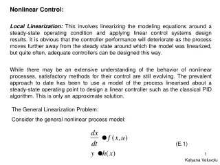
Objective • To design a controller, which guarantees that, for any initial conditions, any constant reference output r and any constant disturbance input w, we have
Proposed PI Control • Reference: Açikmeşe, A. B., & Corless, M. (2002). Robust output tracking for uncertain/nonlinear systems subject to almost constant disturbances. Automatica, 38, 1919-1926
Consider a dynamical system: • Proposed PI Control • Where Kp and Ki are constant matrices of appropriate dimensions
Additional state • Leads to the augmented state vector
And the augmented system • Where,
One may arrive at the matrices defining the derivative augmented system as follows.
The derivative augmented system is quadratically stable via linear state feedback if there exists matrices such that for all x,u,w
System Description • dc-dc Converter Module
States: Constant Disturbance Input: Controller Input Output
Load: • Constant Power Load • Therefore • The load may be changed as necessary (Shown on the result slides)
Result • K = [ 0.4961 2.3211 0.0562] • Slight modification to the input controller to guarantee that
Implement the control along with the converter module model in ACSL (Advanced Continuous Simulation Language) • Error Model:
Study 1: Error = 0.0167
Conclusion Comparison to other methods: • Pole Placement • Genetic Algorithm (GA) • Possible improvement: • Faster transient • Investigate the behavior on Study 4 and figure out why it behaves that way • Implement the controller for a switch level model