Download
1 / 11

E N D
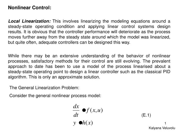
Nonlinear Control: Local Linearization:This involves linearizing the modeling equations around a steady-state operating condition and applying linear control systems design results. It is obvious that the controller performance will deteriorate as the process moves further away from the steady state around which the model was linearized, but quite often, adequate controllers can be designed this way. While there may be an extensive understanding of the behavior of nonlinear processes, satisfactory methods for their control are still evolving. The prevalent approach to date has been to use a model of the process linearised about a steady-state operating point to design a linear controller such as the classical PID algorithm. This is only an approximate solution. The General Linearization Problem: Consider the general nonlinear process model: (E.1) Kalyana Veluvolu
where f(*,*) is an arbitrary nonlinear function of two variables, x, the process state variable, and u the process input; h(*) is another nonlinear function relating the process output, y to the process state variable x. The linearized approximation of this very general nonlinear model (E.1) may now be obtained by carrying out a Taylor series expansion of the nonlinear functions around the point (xs, us), this gives: + higher order terms + higher order terms Ignoring the higher order terms now gives the linear approximation:
(E.2) where It is customary to express the equation in terms of deviation variables:
In addition to this, the linearization point (xs,us) is choosen to be a steady-state operating condition, then observe from the definition of a steady-state that boty dxs/dt and f(xs,us) will be zero (E.2) the becomes (E.3) Where for simplicity, the arguments have been dropped from a, b and c. A transform-domain transfer function model may now be obtained by the usual procedure, the results is: (E.4) with the transfer function as indicated in the square brackets. This transfer function should provide an approximate linear model valid in a region close to (xs,us)
Fi A h F Liquid Level System The principles involved in obtaining approximate linear models by linearization may now be sumarized as follows: • Identify the functions responsible for the nonlinearity in the system model. • Expand the nonlinear function as a Taylor series around a steady-state. • Reintroduce the linearized function into the model; simplify, and express the resulting model in terms of deviation variables. Example: linearization of a nonlinear model involving a nonlinear function of a single variable Consider a Liquid Level System shown as in the figure. Material balance equation yields c c is the flow resistance
y f(x)=f(xs)+f‘(xs)(x-xs) y=f(x) f(xs) xs x Combining two equations yields This is a nonlinear equation. To linearise this equation, one can use Taylor’s series. That is, around h=hs. + higher order terms The approximation is shown as in the figure.
The steady-state flow is and we have where
U(s) Y(s) Y(s) R(s) + Gc(s) G(s) - The linearized system is given as Linearized Liquid Level System (about h = hs) This figure shows a feedback loop where a Proportional and Integral (PI) controller controls the linearized liquid level system. Notice that the linearized system is an approximation since it is derived for a particular level h = hs. If the level changes, K and τ will change with it as well.
where Assuming the closed loop poles to be at the locations -2±2i, which corresponds to the roots of the characteristic equation, for a linearized system with K = 2.38 and τ=0.59, we have Kp=0.58 and τi=0.29. The characteristic equation can be put as
0.1 Im ζ=cos()=2/2.8284=0.707 2 Re -2