Download
1 / 11
200 likes | 458 Views
HARMONIC PROBLEMS IN CAPACITOR BANKS. QUALITY AND TECHNOLOGY. quality of the. electrical energy. HARMONIC PROBLEMS IN CAPACITOR BANKS. Common problems:.

E N D
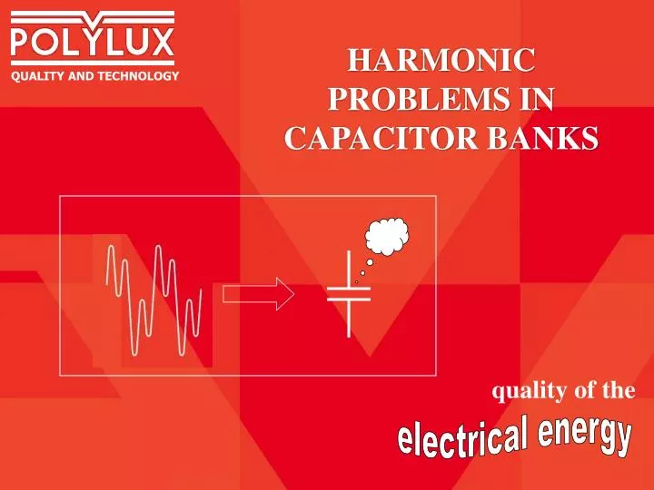
HARMONIC PROBLEMS IN CAPACITOR BANKS QUALITY AND TECHNOLOGY quality of the electrical energy
HARMONIC PROBLEMS IN CAPACITOR BANKS Common problems: Nowadays more and more harmonic generating loads are used (frequency converters, UPS, soft starters, etc.) causing elevated levels of harmonics. Capacitor banks provide power factor correction to correct low cos-phi. When used in electrical installations where harmonics are present, the application of a conventional capacitor bank is likely to suffer and cause several problems: 1) Failure and short lifetime of power capacitors 2) Elevated voltage harmonics 3) Danger of resonance between capacitor bank and main transformer
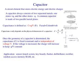
HARMONIC PROBLEMS IN CAPACITOR BANKS Problem 1: Failure of capacitors The current through the capacitor depends on the impedance of the capacitor. The impedance of the capacitor is much lower for higher frequencies (harmonics). Therefore harmonics in the voltage cause elevated additional harmonic currents through the capacitor which overload and damage the capacitor Current through the capacitor Icap = V / Zcap Impedance Zcap Zcap = 1 /(2 f C) Z1 Example: 3% of 5th harmonic in voltage causes 15% additional current through capacitor Z3 Z5 Frequency f 3rd harmonic 5th harmonic fundamental
HARMONIC PROBLEMS IN CAPACITOR BANKS Problem 2: Elevated voltage harmonics RESONANCE The capacitance ‘C’ of the capacitor bank and the inductance ‘L’ of the main transformer and cables form an L-C circuit with certain resonance frequency. In case the resonance frequency is close to one of the present harmonics, this harmonic will be amplified, especially in the voltage. Harmonics cause overheating and malfunction of equipment. L DISTRIBUTION TRANSFORMER HARMONICS OF THE SAME FREQUENCY C CAPACITOR BANK Example: 30% of harmonics in the current, will normally cause around 3% harmonics in the voltage. However a capacitor bank may increase the voltage harmonics to 8% or more. Tip: To know the effect of the capacitor bank on the harmonics, compare measurements of harmonics with and without connected capacitor bank.
HARMONIC PROBLEMS IN CAPACITOR BANKS Problem 3: Resonance DISTRIBUTION TRANSFORMER In case the resonance frequency of the LC circuit formed by the capacitor bank and the main transformer coincide with a present harmonic in the installation, a complete resonance can occur. The resonance may have destructive results for the capacitor bank, main transformer and main switchboard. L HARMONICS OF THE SAME FREQUENCY C DESTRUCTIVE RESONANCE CAPACITOR BANK Note: Resonance is a serious risk which shall not be under estimated, especially in installations with low impedance.
HARMONIC PROBLEMS IN CAPACITOR BANKS Solution: Filtering inductors RTFX RTLX filtering inductor The filtering inductor provides a high impedance for high frequencies (harmonics). The total impedance of the capacitor + inductor step is inductive above the so-called ‘resonance frequency’ L Total current I = V / Ztotal L + C C Impedance |Z| Z = 2 f L + 1 /(2 f C) • Benefits: • High impedance for harmonic frequencies: avoids high harmonic currents through the capacitor • Inductive impedance above resonance frequency: avoids amplification of harmonics and risk of resonance Capacitive impedance Inductive impedance Z1 Z5 Z3 Resonance frequency Frequency f fundamental 3rd harmonic 5th harmonic
HARMONIC PROBLEMS IN CAPACITOR BANKS Technical considerations 1 RTLX filtering inductor The resonance frequency is normally chosen at 189Hz (p=7%), however, in case significant 3rd harmonics are present, it is recommended to choose 135Hz (p=14%) L Total current I = V / Ztotal L + C C Impedance |Z| The resonance frequency depend on the capacitor C and the inductor L, it is very important that both components are well tuned to each other. A wrong resonance frequency may result in harmonic absorption causing damage. Both capacitance and inductance values must therefore be correct and stable to guarantee correct tuning Z = 2 f L + 1 /(2 f C) Capacitive impedance Inductive impedance Z1 Z5 Z3 Resonance frequency Frequency f fundamental 3rd harmonic 5th harmonic
HARMONIC PROBLEMS IN CAPACITOR BANKS Technical considerations 2 Over voltage: 189Hz: 7,5% 135Hz: 14% Filtering inductors cause a higher voltage on the capacitor terminals. The capacitors should therefore be suitable for this higher voltage. L C Examples, for a 400V, 50Hz network: Inductors tuned to 189Hz (p=7%): Use capacitors for 440V, 460V, 480V, 500V or 525V Inductors tuned to 135Hz (p=14%): Use capacitors for 480V, 500V or 525V The effective kvar rating of the capacitor + inductor is calculated as follows: 189Hz: P_eff = (V_line/V_cap)2 x 1,075 x P_cap 135Hz: P_eff = (V_line/V_cap)2 x 1,14 x P_cap Example: line: 400V, 50Hz, capacitor: 440V, 50kvar inductor tuned to 189Hz: P_eff= (400/440)2 x 1,075 x 50 = 44,4 kvar Note: Filtering inductors are recommended for electrical installations where the level of voltage harmonics THD%(V) is 2,5%..3% or more
HARMONIC PROBLEMS IN CAPACITOR BANKS RTFX FILTERING INDUCTOR FOR CAPACITOR BANKS • ADVANTAGES: • - Copper Windings • Problem free terminals • Class F insulation • Low temperature rise (< 90ºC) • Competitive prices
HARMONIC PROBLEMS IN CAPACITOR BANKS Standard characteristics RTFX POLYLUX, S.L. C/ Boters 3b Parc Tecnològic del Vallès 08290, Cerdanyola del Vallès (Barcelona) Spain tel.:+34-936926565 fax: +34-935809603 polylux@polylux.com www.polylux.com Other characteristics on request (please indicate line voltage / frequency and capacitor rating / voltage / frequency)
HARMONIC PROBLEMS IN CAPACITOR BANKS For elimination of harmonics of the electrical network, we offer: • Compensator Harmonic filters • - A new concept in harmonic filtering - • Filtering of 3rd, 5th, 7th, 9th, 15th, 17th and 19th harmonic • Several advantages with respect to other filters in the market: • - Very good filtering level for competitive price • - No electronics or capacitors, maintenance free and very reliable • No generation of high frequency distortions • No exhaustive study of the installation is necessary • Optionally with galvanic isolation Ask for our catalogue