Download
1 / 6
80 likes | 261 Views
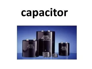
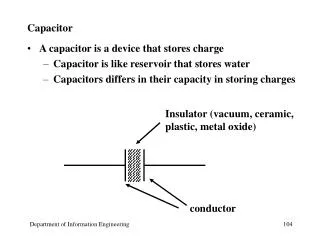
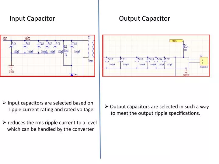
Input Capacitor. Output Capacitor. Input capacitors are selected based on ripple current rating and rated voltage. reduces the rms ripple current to a level which can be handled by the converter. Output capacitors are selected in such a way

E N D
Input Capacitor Output Capacitor • Input capacitors are selected based on • ripple current rating and rated voltage. • reduces the rms ripple current to a level • which can be handled by the converter. • Output capacitors are selected in such a way • to meet the output ripple specifications.
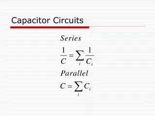
Snubber Circuit on the Secondary Side • Provides damping of the parasitic resonances in the power stage • ( transformer leakage inductance, Llk& diode parasitic capacitance, Cp)
Leakage inductance & Parasitic capacitance can be determined • by solving the following equation simultaneously: Where fosc is the oscillating frequency and C is the capacitor value • Appropriate resistor value and the power it must • dissipate is determined from: Where V is the sum of drain to source voltage to the Secondary side and the voltage drop across the diode. PR = C . V2 . fsw
RCD Voltage Snubber on the Primary Side Used to suppress the voltage overshoot across the FET caused by the transformer inductance during turn-off transition of the switch
The resistor value is selected so that it can dissipate the energy • stored in the leakage inductance and the DC bias of the capacitor. • The minimum capacitor value can be estimated from the following • relationship: Secondary side voltage reflected to the primary Voltage change across the capacitor
IC Voltage Regulator • LM78L15ACM-ND three- terminal regulator provides a constant DC • output voltage required to baisthe controller. • Coupling and decoupling capacitors are placed close to the input and • out pins of the regulator respectively to reduce ripple voltage amplitude.