Download
1 / 47
870 likes | 3.01k Views
Combinational Logic in Verilog. Verilog for Combinational Circuits How can Verilog be used to describe the various combinational building blocks? Can always use structural style This can get tedious “Data flow” style is more convenient assign x = a & ~b (etc, etc)

E N D
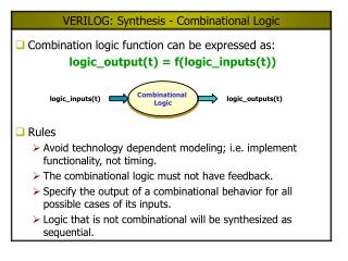
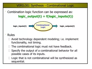
Verilog for Combinational Circuits • How can Verilog be used to describe the various combinational building blocks? • Can always use structural style • This can get tedious • “Data flow” style is more convenient • assign x = a & ~b (etc, etc) • Behavioral style is also good – we’ll look at this shortly
Verilog: 2x1 MUX • Uses the conditional ?: operator • Software designers detest this operator • Hardware designers revel in its beauty
Verilog: 4x1 MUX (Data Flow Style) • This is getting complicated! • Need a way to specify a “group” of bits like w[0:3] • Need a way to replace ?: with “if then else”
Vectored Signals in Verilog • Signals can be grouped as bit vectors • The order of the bits is user determined • W has 4 lines with the MSB = W[0] and the LSB = W[3] • S has two lines with the MSB = S[1] and the LSB = S[0] Format is [MSB:LSB]
s 0 s 1 w 0 w 3 s w 2 4 s 3 w 7 f w 8 w 11 w 12 w 15 • Hierarchical Design of a 16x1 MUX Structural style Verilog The Verilog code for mux4x1 must be either in the same file as mux16x1, or in a separate file (called mux4x1.v) in the same directory as mux16x1
w y w y 0 0 0 0 w y w y 1 1 1 1 y y 2 2 y y En 3 3 y w y 4 0 0 w y y 1 1 5 y y 2 6 w w y y y 2 En 0 0 3 7 w w y 3 1 1 y 2 y w y y w En En 8 0 0 3 y w y 1 1 9 y y 2 10 y y En 3 11 y w y 12 0 0 w y y 1 1 13 y y 2 14 y y En 3 15 • Hierarchical Design of a 4 to 16 Decoder Structural style Verilog dec2to4 to be presented soon ….
Behavioral Style in Verilog Must be reg type when used as LHS in an always block Sensitivity list: statements inside the always block are only executed when one or more signals in the list changes value
Always Blocks • All LHS signals must be variables type reg • The simulator registers the value and maintains it until the statements in the always block are executed again • Statements are re-executed only when a signal in the sensitivity list changes value • The sensitivity list must include all signals on which the LHS variables depend in the always block • Order counts inside the always block!!!! • If … else is called a procedural statement • All procedural statements must be inside an always block
Single vs Multiple Statements • In Verilog, all constructs permit only a single statement • If you need > 1 statement inside a construct, use begin … … end • This is similar to Pascal syntax • Verilog is generally more like C though You won’t find much use for begin … end most constructs really do include just a single statement
Representation of Numbers • Numbers can be given as constants in • Binary (b) • Octal (o) • Hex (h) • Decimal (d) • For numbers of a specified size: • TFAE: • 12’d2217 • 12’h8A9 • 12’o4251 • 12’b100010101001 Numbers are 0-extended to the left, if necessary, to fill out the number of bits If the value exceeds the # of bits allocated, the extra bits are ignored! #bits given in decimal
More on Representation of Numbers • Negative numbers: • -4'b101 the 4 bit 2’s complement of 5 1011 • For numbers of an unspecified size: • TFAE: • 2217 • ’d2217 • ’h8A9 • ’o4251 • ’b100010101001 • The Verilog compiler chooses the size to fit with the other operands in the expression
Case Statement Comparisons in a case statement are made bit by bit. No break statement needed – first match executes and then case is exited. Use begin … end if > 1 statement required in a case. If not all cases are enumerated, make sure to use default case.
4 to 2 Binary Encoder Left extended by x to fill 2 bits
4 to 2 Priority Encoder casex vs case
Case, Casez, Casex • Case treats each value 0, 1, x, and z literally • 4’b01xz only matches 4’b01xz • Example: 4’b0110 does not match 4’b01xx in a case • Casez treats 0, 1, and x literally • Casez treats z as a don’t care • Example: 4’b0110 matches 4’b01zz, but not 4’b01xz • Casex treats 0 and 1 literally • Casex treats both x and z as don’t cares • Example: 4’b0110 matches 4’b01xx and also 4’b01xz No match here
For Loop • When a circuit exhibits regularity, a for loop can be used inside an always statement to simplify the design description (for loop is a procedural statement only inside an always block) • C style syntax: for (k = 0; k < 4; k = k+1) • Loop index must be type integer (not reg!) • Can’t use the convenience of k++ • Use begin … end for multiple statements in the loop • Each iteration of the loop specifies a different piece of the circuit • Has nothing to do with changes over “time”
4 to 2 Priority Encoder Using a For Loop A signal that is assigned a value multiple times in an always block retains its last value priority scheme relies on this for correct setting of Y and z
Machine Arithmetic • Arithmetic combinational circuits are required for • Addition • Subtraction • Multiplication • Division (hardware implementation is optional) • Addition / subtraction can be done easily using full adders and a minimum of additional logic
x y x y x y 1 1 0 0 n – 1 n – 1 c 1 c c c c FA FA FA n - 1 n 0 2 s s s n – 1 1 0 MSB position LSB position • Ripple-Carry Adder • A ripple carry adder cascades full adders together • Simple, but not the most efficient design • Carry propagate adders are more efficient
Behavioral Style Full Adder • We’ve done full adders many ways already data flow styles behavioral style
Behavioral Style Ripple-Carry Adder Allows a generic size to be specified For n = 2, the for loop is equivalent to: S[0] = X[0] ^ Y[0] ^C[0];C[1] = (X[0] & Y[0]) | (X[0] & C[0]) | (Y[0] & C[0]);S[1] = X[1] ^ Y[1] ^C[1];C[2] = (X[1] & Y[1]) | (X[1] & C[1]) | (Y[1] & C[1]);
Higher Level Behavioral Style for Adder • This won't work! Can't loop over “subcircuits” subcircuits to be instantiated like this are not allowed in a for loop
Functions / Tasks • Subcircuits can't directly be instantiated in for loops • Can’t create a separate module for fulladder and then instantiate that inside a for loop • Need to create a function or a task for the subcircuit • Functions and tasks provide modular code without defining separate modules • Defined within a module • Code is placed in-line by the Verilog compiler • Functions and tasks are behavioral only
Functions • Functions provide modular code without defining separate modules • Defined within a module • Can have many inputs (must have > 0), but only one output • Function is called like C++ functions that have a non-void return value • Functions can be called in a continuous assignment or in a procedural statement • Functions contain only procedural statements • Function code is placed in-line by the Verilog compiler
More on Functions • Functions must have > 0 inputs • Order of inputs is dictated by the order in which they are declared in the function • Functions can call other functions, but not tasks • May return a vectored signal by declaring the function as: function [3:0] foo; // the range indicates a 4 bit result…endfunction
Function Example: 16x1 MUX begin … end required if more than 1 procedural statement in a function
Tasks • Tasks also provide modular code without defining separate modules • Also defined within a module • Can have many inputs and outputs • Task is called like C++ functions that have a void return type • Outputs are returned via the output variables (like the ports in a module) • Task can only be called in a procedural statement • Tasks contain only procedural statements • Task code is placed in-line by the Verilog compiler
More on Tasks • Tasks may have any number of inputs and outputs • Order of inputs and outputs is dictated by the order in which they are declared in the task • Tasks can call other tasks or functions • All arguments to a task are implicitly of type reg • begin … end block required in a task if you use > 1 procedural statement
Generate Statement • Verilog 2001 provides a new statement for instantiating separate modules inside a for loop • Permits structural style to use for loops • generate … endgenerate • Use genvar datatype in place in integer
Ripple-Carry Adder Using Generate compiler produces n modules with names addstage[0].addbit, addstage[1].addbit, …, addstage[n-1].addbit
y y y n – 1 1 0 ¤ Add Sub control x x x n – 1 1 0 c c n -bit adder 0 n s s s n – 1 1 0 • Subtractors • Subtraction is the same as addition • X – Y = X + (-Y) where –Y is the 2’s complement of Y • 2’s complement: -Y (~Y) + 1 • Complement every bit of Y and add 1 • Another way is (Y (11…11)) + 1
Macrofunctions • Libraries of common circuits, such as adders, are available in most commercial CAD tools • Sometimes called macrofunctions or megafunctions • Example: Quartus II provides a Library of Parametrized Modules (LPM) • Each module is parametrized, e.g. the user can set the number bits used in the module • LPM_ADD_SUB is an n-bit adder / subtractor where you can pick the n it will use • LPM_WIDTH • Available in the “megafunctions arithmetic” library
LPM_ADD_SUB Module • add_sub = 1 dataa + datab + cin • add_sub = 0 dataa - datab + (cin-1) Multi-bit signals must be named with [MSB..LSB]
Sample Application: BCD Adder • Build a 4 bit BCD adder with carry-out • Examples: • What’s the rule??? • If the binary sum exceeds 9 (including the carry out), then add an additional 6 to it to get the BCD sum • cout = 1 if cout from binary add, or if cout from +6 add
A compute cout cout Adjust = (carry-out) | (Z[3] & (Z[2] | Z[1])) cout • Block Diagram for BCD Adder
Structural Verilog for BCD Adder Using positional notation for argumentsNote: add_sub = 1 is the default and so need not be specified Specifying the size of theadders using defparam
Timing Diagram for BCD Adder Z from adder1 A from 2x4 mux = 0 or 6
74381 TTL 4-Bit ALU • The 74381 TTL ALU (arithmetic logic unit) has the following 4 bit operations available for use with carry-lookahead adders