Download
1 / 28
350 likes | 1.13k Views
MICROCONTROLLER LAB- 8051. Balaji Ramakrishna. Microcontrollers. Memory. ROM RAM. CPU. I/O. Subsystems: Timers, Counters, Analog Interfaces, I/O interfaces. A single chip. Pin Diagram. Common Microcontrollers. Atmel ARM Intel 8-bit 8XC42 MCS48 MCS51 8xC251 16-bit

E N D
MICROCONTROLLER LAB- 8051 Balaji Ramakrishna
Microcontrollers Memory ROM RAM CPU I/O ECE/CS-352: Embedded Microcontroller Systems Subsystems: Timers, Counters, Analog Interfaces, I/O interfaces A single chip
Common Microcontrollers • Atmel • ARM • Intel • 8-bit • 8XC42 • MCS48 • MCS51 • 8xC251 • 16-bit • MCS96 • MXS296 • National Semiconductor • COP8 • Microchip • 12-bit instruction PIC • 14-bit instruction PIC • PIC16F84 • 16-bit instruction PIC • NEC • Motorola • 8-bit • 68HC05 • 68HC08 • 68HC11 • 16-bit • 68HC12 • 68HC16 • 32-bit • 683xx • Texas Instruments • TMS370 • MSP430 • Zilog • Z8 • Z86E02
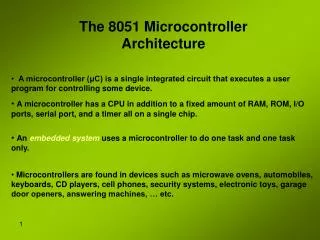
The necessary tools for a microprocessor/controller • CPU: Central Processing Unit • I/O: Input /Output • Bus: Address bus & Data bus • Memory: RAM & ROM • Timer • Interrupt • Serial Port • Parallel Port
Microcontroller Architectures Memory 0 Program + Data Address Bus Von Neumann Architecture CPU Data Bus 2n Memory 0 Program Address Bus Harvard Architecture Fetch Bus CPU Address Bus 0 Data Data Bus
“Original” 8051 Microcontroller 4096 Bytes Program Memory 128 Bytes Data Memory Two 16 Bit Timer/Event Counters Oscillator and timing Internal data bus 8051 CPU Programmable I/O Programmable Serial Port Full Duplex UART Synchronous Shifter 64 K Byte Bus Expansion Control subsystem interrupts External interrupts Parallel ports Address Data Bus I/O pins Control Serial Output Serial Input
7FH Scratch pad RAM 30H 2FH Bit-Addressable RAM 20H 1FH Register Bank 3 18H 17H Register Bank 2 10H 0FH (Stack) Register Bank 1 08H 07H Register Bank 0 00H • RAM memory space allocation in the 8051
Bit Addressable RAM Figure 2-6 Summary of the 8051 on-chip data memory (RAM)
The EA' (External Access) pin is used to control the internal or external memory access. The signal 0 is for external memory access and signal 1 for internal memory access. The PSEN' (Program Store Enable) is for reading external code memory when it is low (0) and EA is also 0.The ALE (Address Latch Enable) activates the port 0 joined with port 2 to provide 16 bit external address bus to access the external memory. The ALE multiplexes the P0: ALE=1 for latching address on P0 as A0-A7 in the 16 bit address buss, ALE=0 for latching P0 as data I/O.P0.x is named ADx because P0 is multiplexed for Address bus and Data bus at different clock time. WR' provides the signal to write external data memory RD' provides the signal to read external data and code memory.
There are 4 8-bit ports: P0, P1, P2 and P3. All of them are dual purpose ports except P1 which is only used for I/O. The following diagram shows a single bit in an 8051 I/O port. When a program writes a one byte value to a port or a single bit value to a bit of a port, assigning the value to the port as follows: P1 = 0x12; or P1^2=1; P1 represents the 8 bits of port 1 and P1^2 is the pin #2 of the port 1 of 8051 defined in the reg51.h of C51, a C dedicated for 8051 family. When data is written to the port pin, it first appears on the latch input (D) and is then passed through to the output (Q) and through an inverter to the Field Effect Transistor (FET). If you write a logic 0 to the port pin(DFF Q=0), it is inverted to logic 1 and turns on the FET gate. It makes the port pin connected to ground (logic 0). If logic 1 is written to the port pin(DFF Q=1), , then it is inverted to a logic 0 and turns off the FET gate. Therefore the pin is at logic 1 because it is connected to high.
PORT P1 (Pins 1 to 8): The port P1 is a port dedicated for general I/O purpose. The other ports P0, P2 and P3 have dual roles in addition to their basic I/O function. • PORT P0 (pins 32 to 39): When the external memory access is required then Port P0 is multiplexed for address bus and data bus that can be used to access external memory in conjunction with port P2. P0 acts as A0-A7 in address bus and D0-D7 for port data. It can be used for general purpose I/O if no external memory presents. • PORT P2 (pins 21 to 28): Similar to P0, the port P2 can also play a role (A8-A15) in the address bus in conjunction with PORT P0 to access external memory.
PORT P3 (Pins 10 to 17): • In addition to acting as a normal I/O port, • P3.0 can be used for serial receive input pin(RXD) • P3.1 can be used for serial transmit output pin(TXD) in a serial port, • P3.2 and P3.3 can be used as external interrupt pins(INT0’ and INT1’), • P3.4 and P3.5 are used for external counter input pins(T0 and T1), • P3.6 and P3.7 can be used as external data memory write and read control signal pins(WR’ and RD’)read and write pins for memory access.