Download
1 / 33
330 likes | 444 Views
Maximally Adaptive Routing. Maximize adaptivity for a double-x routing based on turn model. Virtual network 0. Virtual network 1. Maximally adaptive double-x (mad-x). Opt-x algorithm. The Mad-x algoritm is improved by reducing the routing ristrictions on the VCs. Virtual network 0.

E N D
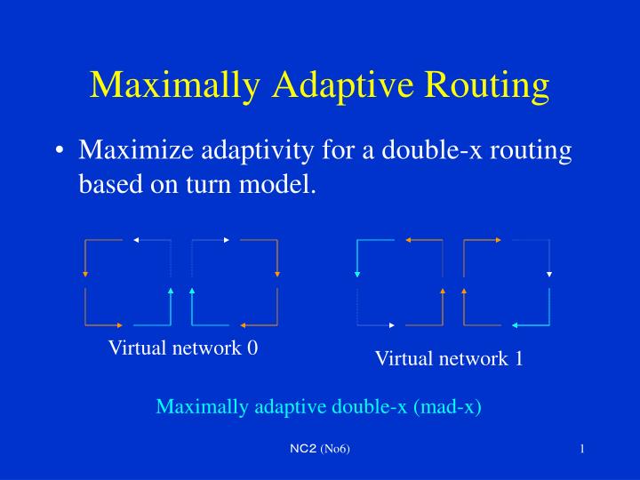
Maximally Adaptive Routing • Maximize adaptivity for a double-x routing based on turn model. Virtual network 0 Virtual network 1 Maximally adaptive double-x (mad-x) NC2 (No6)
Opt-x algorithm • The Mad-x algoritm is improved by reducing the routing ristrictions on the VCs. Virtual network 0 Virtual network 1 optimal adaptive double-x (opt-x) NC2 (No6)
Nonminimal routing • Randomized routing (Valiant’s algorithm) is an example of nonminimal routing. It selects intermediate node randomly to balance the load. • For networks using wormhole switching, nonminimal routing algorithms usually degrade performance because packets consume more network resources. • So they are usually proposed for fault-tolerant routing to find alternative paths when all the minimal paths are faulty. NC2 (No6)
Backtracking protocols (1/2) • Backtraking protocols work on the premise that it is better to be searching for alternative paths than to be waiting for a channel to be available. • From a performance point of view, backtracking protocols are suited to circuit switching. • Although backtracking can be implemented with SAF switching, the performance overhead is substantial. NC2 (No6)
Backtracking protocols (2/2) • Most backtracking protocols use the routing header to store history information, thus increasing the size and transmission time of it. • History information can be distributed throughout the nodes of networks. • Each input link has a history bit vector to remember the corresponding output channel. NC2 (No6)
Exhaustive profitable backtracking(EPB) • It performs depth-first search of the network using only profitable (minimal) links. • K-family routing protocols use a heuristic to minimize redundancy in the search for a path. • In K-family, cumulative history mask of the ancestor nodes is utilized. NC2 (No6)
EPB and K-family 000 111 110 x x 100 101 001 010 100 011 010 011 101 011 110 101 110 001 x x x x 000 111 111 111 111 111 111 NC2 (No6)
Exhaustive misrouting backtracking • It does a depth-first search of the network using both profitable and unprofitable links. 000 111 110 x x 001 010 100 100 101 011 010 011 101 011 110 101 110 x x x x 001 000 111 111 111 111 111 111 NC2 (No6)
Routing in MINs • In MINs, blocking occurs when two packets must traverse the same output at a switch stage. • Blocking condition for the Omega network can be tested by comparing the addresses of two input/output pairs. (equivalent conditions can be derived for other networks in a similar manner.) NC2 (No6)
Blocking condition for an Omega network (1/2) • To route (an,an-1,an-2,…, a1) to (bn,bn-1,bn-2,…, b1), First stage connects (an,an-1, …, a1) to (an-1,an-2,…, a1, an) and an should be equal tobn. • The address of the intermediate output at each stage can be shown as the following. an an-1 an-2 … a1 bn bn-1 bn-2 … b1 • Testing for blocking between two input/ output pairs is done by the comparisons of these windows. NC2 (No6)
Blocking condition for an Omega network (2/2) 000 000 001 001 010 010 011 011 100 100 101 101 110 110 111 111 1 0 00 1 0 0 0 00 0 1 NC2 (No6)
Switch-based networks • Switch-based interconnections, such as Myrinet are used to build network of workstations or PCs. • Typically, these switches support networks with irregular topologies. • Such irregularity provides the wiring flexibility in LANs for scalable systems with incremental expansion. NC2 (No6)
Myrinet • Miricom, Inc. produced NIC and switches based on technology developed at CALTECH Univ. • 2.0+2.0 Gb/s (Myrinet2000) • Cut-through routing http://www.myricom.com/ NC2 (No6)
Myrinet switch • A building block of the Myrinet switch is the 16-port crossbar switch which is mounted on a line card to connect 8 hosts with 8 ports of the backplane. • Any topology is allowed. NC2 (No6)
Myrinet switch enclosure • Myrinet "Network in a Box" components that can interconnect up to 128 hosts with a single, full-bisection, network component, and up to tens of thousands of hosts by combining these components. Clos network for 128 hosts with all Fiber ports and monitoring capability NC2 (No6)
A 32-host Clos network backplane 4 links each XBar16 8 hosts 8 hosts 8 hosts 8 hosts NC2 (No6)
Routing of Myrinet • Only the first byte of the header is examined when the packet enters a switch or interface. Once this byte is used to select an outgoing port of a switch, it is discarded (stripped) from the head of the packet. NC2 (No6)
Routing in irregular topology • Routing tables are required (e.g. DEC Autonet). • Some mapping algorithm must be executed to fill those tables before routing can be performed. • Autonet computes a breadth-first spanning tree (BFS) to fill the routing tables [Schroeder,99]. NC2 (No6)
An example of irregular topology 3 0 5 6 switches 1 4 8 hosts 7 2 NC2 (No6)
Up/down routing (1/2) • Pick up one node as a root • Construct a spanning tree • Decide the up direction to the node closer to the root, or to the lower ID at the same level • Opposite directions against up are defined as down • A legal route must traverse zero or more links in the up direction followed by zero or more links in the down direction 6 5 1 4 3 7 2 2 8 NC2 (No6)
Up/down routing (2/2) • Cyclic dependencies between channels are avoided because a packet may never traverse a link along the up direction after having traversed one in the down directions. • It is not able to supply any minimal path between some pairs of nodes. (e.g. the shortest path from switch 3 to 2 through switch 8 is not allowed) NC2 (No6)
Adaptive routing for irregular topology (1/2) • Given an interconnection network and a deadlock-free routing function defined on it. • Split all the physical channels in the network into two VCs, original and new. • Newly injected messages can use the new VCs without any restriction as long as the original VCs can only be used in the same way as in the original routing function. • Once a message reserves one of the original VCs, it can no longer reserve any of the new VCs again. NC2 (No6)
Adaptive routing for irregular topology (2/2) • New channels can be used to route minimal paths. • Because the original channels provide nonminimal paths in most cases, newly injected messages should be leave the source switch using the new channel. (higher priority to the new channels) NC2 (No6)
Resource allocation policies • network resources are required to arbitrate between several packets contending for the same resource. • selecting a channel or buffer among the options offered by an adaptive routing is referred as selection function. • The selection function selects an output channel form the set of channels supplied by a routing function. NC2 (No6)
An example of DP a 0 1 2 3 b b a Output channels are selected form a set of blue channels on each node. 4 5 6 7 8 9 a b c d e f NC2 (No6)
Selection policies • Random: network state is not considered (oblivious routing) • Minimum congestion: the most available VCs are selected to balance the use of them • Maximum flexibility: a VC is selected in the dimension with the greatest distance • Straight lines: a VC is selected in the dimension closest to the current dimension (a good distribution of traffic for 2-D meshes) NC2 (No6)
Time-dependent selection function • Performance may degrade if packets take long to escape form deadlock. • To increase the availability of escape VCs, a selection function may delay the use of escape VCs by using a timeout. • Deadlock recovery mechanisms only select escape channels after a timeout. NC2 (No6)
Real-time communication • Best-effort packets and guaranteed packets compete for network resources. • VCs are split into two virtual networks assigning best-effort and guaranteed packets. • Packets corresponding to different priority classes can be achieved by using packet switching with a scheduling mechanism (e.g. earliest deadline first). NC2 (No6)
VC allocation • It is required when several VCs belonging to the same physical channel are ready to transfer a flit. • Random: arbitrary order • Round-robin: circular order • Priority scheme: some information carried in the packet header is used NC2 (No6)
Throughput fairness 0.75 0.5 0.25 0.5 0.25 0.5 0.25 Equal bandwidth to three flows on a shared channel 0.75 0.15 0.15 0.5 0.3 0.5 0.3 Max-min fairness that the allocation to any flow cannot be increased without decreasing the allocation to a flow that has an equal or lesser allocation. NC2 (No6)
Latency fairness D1 C1 B1 A1 D2 C2 B2 A2 Locally fair arbitration: A1, B1, A2, C1, A3, B2, A4, D1, A5, … Age based arbitration: A1, B1, C1, C1, D1, A2, B2, C2, D2, … NC2 (No6)
Non-interfering networks • Allocating resources based on classes allows us to prioritize services. • We may give packets of higher class strict priority in allocation of buffers and channels over packets of a lower class. • To achieve isolation between two classes A and B, non-interfering networks does not allow to interrupt the usage of resources for A by B. • The number of classes should be carefully chosen by the designer because of hardware complexity. NC2 (No6)
Routing function unit • A routing function is implemented by a single unit or several units in the input VCs. • In the former case, several packets contend for the unit, requiring arbitration. • Input driven: input VCs form a logical circular list and are selected in round-robin • Output driven: keep a pointer to the next free output channel, and select a packet to be routed it NC2 (No6)