Download
1 / 56
680 likes | 1.02k Views
AASHTO – LRFD OF STEEL BEAM BRIDGES Fatigue and Fracture. Special course on of AASHTO LRFD Specifications Workshop # 4 – Day 2. by, Amit H. Varma. May 2, 2003 Michigan Department of Transportation Conference Room. INTRODUCTION Some examples of fatigue prone details.

E N D
AASHTO – LRFD OF STEEL BEAM BRIDGES Fatigue and Fracture Special course on of AASHTO LRFD Specifications Workshop # 4 – Day 2 by, Amit H. Varma May 2, 2003 Michigan Department of Transportation Conference Room
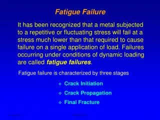
FUNDAMENTAL FATIGUE OF METALS • Metal fatigue is a well-known phenomenon • Wohler - German engineer – fatigue of railroad car axles • Alternating cyclic stresses (even in the elastic range) cause fatigue failure in metal components or details. • Fatigue crack initiation • Fatigue crack propagation • Brittle fracture • The cyclic stress range causes the initiation of fatigue cracks, fatigue crack propagation, and eventually brittle fracture of the cracked component. • Fundamental fatigue behavior of a metal is expressed in terms of a constant amplitude cyclic stress range vs. number of cycles to failure (Sr - N) curve.
FUNDAMENTAL FATIGUE OF METALS • The Sr – N curve for a metal can be developed by conducting four-point rotating bending tests according to ASTM Standards. • Test specimen is an unnotched mirror-polished smooth cylindrical bar 0.25 in. in diameter • Sr – N curve is a straight line in log-log coordinates • ENDURANCE LIMIT – Se below which infinite fatigue life
Standard rotating bending fatigue test Stress range vs. Number of cycles (Sr – N) to failure.
FATIGUE CRACK INITIATION • Structural components and welded details have inherent flaws or defects, which serve as initial cracks. • These initial cracks propagate to larger sizes and eventually fracture under cyclic fatigue loading. • Smooth structural components with notches or discontinuities • Strain concentrations and localized plastic strains occur at the notches / discontinuities • Alternating cyclic plastic strains cause fatigue crack initiation. • Fundamental constant amplitude strain range (De) versus number of reversals (Nf) to crack initiation for a metal – experimentally • These De – Nf curves can be used to predict crack initiation in smooth components with notches or geometric discontinuities. • Not of much use for bridge structural components and details, which have inherent flaws or defect serving as initial cracks.
FATIGUE CRACK INITIATION • Total strain = elastic strain + plastic strain. • When elastic strains dominate, behavior is similar to the Sr – N behavior of metal. • When plastic strains dominate, the slope of the De – Nf curve changes becomes more steep indicating reduced fatigue life • Usually occurs for 1 < Nf < 1000 – called low cycle fatigue
Fatigue crack initiation at notches or discontinuities Strain amplitude (De/2) vs. number of reversals (Nf) to failure
FATIGUE CRACK PROPAGATION • Initiated cracks propagate to larger sizes under cyclic loading • Stable fatigue crack propagation or crack growth • Fatigue cracks become large – cause unstable crack growth – Fracture • Propagation of fatigue cracks due to cyclic loading can be predicted and understood using fundamentals of fracture mechanics. • Fracture mechanics relates the stress-field in the vicinity of a crack tip to the nominal stress, size, shape, orientation of the crack, and material properties. • Consider the stress state in the vicinity of the crack tip in a structure subjected to tensile stresses normal to the plane of the crack • magnitude described by the stress intensity factor KI , which implicitly accounts for the effects of stress, crack size and geometry, and structure
Stress state in the vicinity of a crack tip loaded in tension
FATIGUE CRACK PROPAGATION • KI can be calculated analytically for various structural configurations, crack geometries, and loadings • For all cases KI = Cs • KIhas units of ksi • Unstable crack growth occurs when KIexceeds KIc, which is the critical stress intensity factor for the material • KIc represents the fundamental fracture toughness of the material, it ability to crack without brittle fracture • ASTM E399 to determine KIc experimentally • Stable crack propagation occurs under cyclic loading if KI < KIc
FATIGUE CRACK PROPAGATION • Stable crack propagation rate – Paris’ Law where, a = flaw or crack size; N = number of fatigue cycles A and m are material constants • Fatigue crack propagation is linear with respect to (DKI) in log-log coordinates
TOTAL FATIGUE LIFE • The total fatigue life of a component is equal to the sum of the crack initiation life and the crack propagation to fracture life • N = Ni + Np • For bridge components and details, initial crack or defects are present in the form of flaws or defects • Crack initiation life is negligible • Crack propagation life dominates (N = Nf) • If the initial flaw size is ai and the final flaw size at fracture is af Therefore Let A1 = Therefore And
FATIGUE LIFE • where, m = 3 for ferrite-perlite steels • The constant A1 depends significantly on the value of the initial flaw or defect ai, which cannot be estimated easily or accurately • Therefore, A1 is calibrated to experimental results for various structural components and details • This equation is identical to the one recommended by AASHTO for fatigue life prediction and design • Experimental results indicate the existence of an endurance limit (Ds)TH below which fatigue crack propagation does not occur
FATIGUE DESIGN PROVISIONS • AASHTO provisions (2000) are based on the load and resistance factored design (LRFD) philosophy • Current LRFD provisions recommend that fatigue should be categorized as load – inducedfatigue or distortion-induced fatigue • Previous standard specification focused on load-induced fatigue only • Distortion induced fatigue caused by unaccounted cyclic stresses produced by distortion or out-of-plane deflections that induced by secondary members (diaphragms or lateral bracing frames) • Load induced fatigue – quantitative analysis • Distortion induced fatigue – qualitative only + detailing practices
FATIGUE LOADING • Fatigue loading for design consists of two parts, namely, the applied cyclic stress range (Df) and the frequency of occurrence or the number of fatigue cycles. • The live-load stress range is used as the relevant force effect for designing bridge details for fatigue. • Research has shown that the total stress is not relevant for welded details • Residual stresses are not considered explicitly for fatigue design • Using the stress range as the design parameter implicitly includes the effects of residual stresses on welded details • Fatigue design load = vehicular live load (LL) due to fatigue design truck and the corresponding impact factor (IM) and centrifugal force (CE) • Q = where, hi = load modifiers, gi= load factor = 0.75 and • The load factor of 0.75 reflects a load level representative of the truck population with large number of repetitive cycles and fatigue effects.
FATIGUE DESIGN TRUCK • Steel bridges are designed for the live-load (LL) stress range caused by the fatigue design truck, which has a set distance of 30 ft. between the 32 kip loads, and is slightly different than the design truck • The live load stress due to the passage of the fatigue load is approx. one-half of the heaviest truck expected to cross the bridge in 75 years. • Only one fatigue truck is considered for design irrespective of the number of design lanes. • No multiple presence of live load and no lane loads are considered. • Dynamic load allowance (IM). The live load stress caused by the fatigue design truck is to be increased by the dynamic load allowance factor of 15%
FATIGUE LOADING • The frequency of occurrence of the fatigue design load is estimated as the single-lane annual daily truck traffic (ADTT)SL • In the absence of better information ADTT)SL can be estimated as (ADTT)SL = p x ADTT • ADTT = number of trucks per day in one direction averaged over the design life • ADTT can be estimated as the limiting value of average daily traffic multiplied by the fraction of trucks in the traffic
FATIGUE LOADING • Fatigue design life = 75 years • Total number of fatigue cycles over the design life • N = (365) (75) n (ADTTSL) Where, n = number of stress range cycles per truck passage • For continuous spans, a distance equal to one-tenth of the span either side of the interior support near the support • n = 5 for cantilever girders due to the vibrations as the truck leave
FATIGUE DESIGN CRITERIA • Fatigue design criteria for load-induced fatigue in a component • h g (Df) ≤ j (DF)n • g = load factor = 0.75; and j = 1.0 for the fatigue limit state • (Df) = maximum stress range (LL, IM, CE) due to the fatigue truck • (DF)n = nominal fatigue resistance of the structural component or detail. • The nominal fatigue resistance for structural components / details • (DF)n = (DF)TH • where N = (365)(75) n (ADTTSL) = number of cycles over design life • (DF)TH is the constant amplitude fatigue threshold in ksi • Commonly existing components and details categorized into detail categories A .. E’ • Values of A and (DF)THare specified for these detail categories
Stress – range vs. number of cycles for various detail categories
FATIGUE RESISTANCE • (DF)THis the constant amplitude fatigue threshold below which the component or detail will theoretically have infinite fatigue life. • (DF)TH values correspond to the allowable fatigue stress range specified by the previous AASHTO standard specifications for more than 2 million cycles on a redundant load path structure • Why is (DF)TH multiplied by ½ ? • to account for the possibility of the heaviest truck in 75 years being double the weight of the fatigue truck used in calculating stress range • Logically, this effect should be present on the load side (Df) instead of the resistance side (DF)n • When (DF)TH controls the resistance, the LRFD equation becomes ½ (DF)TH ≥ g (Df) or (DF)TH ≥ 2 g (Df) • Thus, the effect of double-heavy trucks on the design for theoretically infinite fatigue life is accounted for by multiplying the fatigue threshold (DF)TH by ½ instead of multiplying the applied stress (Df) range by 2
COMPARISON WITH AASHTO Standard In the previous AASHTO standard specifications, allowable stress ranges were specified for both redundant and non-redundant member. • The allowable for non-redundant members were arbitrarily specified as 80% of those for redundant members due to more severe consequences of their failure. • However, greater fracture toughness was also specified for non-redundant members. • This double-penalty has been rectified in the LRFD specifications by maintaining only the requirement for greater fracture toughness for non-redundant members. • The same fatigue resistance curves are applicable to both redundant and non-redundant members.
FATIGUE DETAIL CATEGORIES • Structural components and details are grouped into eight detail categories according to their fatigue resistance • A and B detail categories are for plain members and well-prepared welded connections in built-up members without attachments • D and E detail categories are assigned to fillet-welded attachments and groove-welded attachments without adequate transition radius or with unequal plate thickness • C detail category can apply to welded attachments with transition radius greater than 150 mm and proper grinding of welds.
BUILT-UP MEMBERS PLAIN MEMBERS B B’ E E’ A B E Rolled surface Cont. welded Painted weath. Eyebars Cover plates Splice connection Fastened connections Unequal sections Same sections Bolted Riveted B D B Transitions in width or thick 1:2.5 Width transition 2 ft. radius B B’ B
LONGITUDINALLY LOADED ATTACHMENTS Groove welded Fillet welded Transition radius Transition radius Detail length Detail length End welds not ground smooth End welds not ground smooth End welds ground smooth End welds ground smooth C D E E’ C D E E’ Longer is worse Longer is worse E E B C D E D E R > 2 in. not req Larger radius better
TRANSVERSE LOADED ATTACHMENTS Groove welded Unequal plate thickness Equal plate thick Weld rft. not removed Weld rft. removed Weld rft. removed Weld rft. not removed B C D E C D E E D E Rad. > 6.0 not help R > 2 in. not bet. Larger rad.better
TRANSVERSE LOADED ATTACHMENTS FILLET WELDED CONNECTION Fillet welded Welds parallel to direction of stress Welds normal to stress C at base metal Transition radius and Welds not ground smooth Transition radius and Welds ground smooth Welds normal or par. to stress E in the weld E D E Rad. > 2.0 in. no help
DISTORTION INDUCED FATIGUE • Rigid load paths are required to prevent the development of significant secondary stresses. • Transverse members should be connected appropriately to the longitudinal members • Transverse connection plates should be welded or bolted to both the compression and tension flanges of the cross-section, where • Connecting diaphragms or cross-frames are attached • Internal or external diaphragms or cross-frames are attached • Floor-beams are attached • Corresponding connection should be designed for a force of 20 kips for straight, non-skewed bridges
DISTORTION INDUCED FATIGUE • Lateral connection plates should be attached to the flanges of the longitudinal member, otherwise • Lateral connection plates attached to stiffened webs should be located at a distance of at least the flange width divided by two (bf /2) from the flange-web interface • Connection plates attached to unstiffened webs must be located at a distance of at least 6.0 in. or bf /2from the flange-web interface • This will reduce out-of-plane distortions of the web-gap between the lateral connection plate and the flange-web interface to a tolerable value • It will also move the connection plate closer to the neutral axis, thus reducing the impact of weld termination on fatigue strength
DISTORTION INDUCED FATIGUE • Lateral bracing members should be attached to lateral connection plates at a minimum distance of 4.0 in. from the web or any transverse stiffener. • Reduce distortion-induced stresses in the gap in the lateral connection plate between the web/stiffener and the lateral bracing members • If web stiffener is present at the same location at the lateral connection plate, then the plate should be centered on the stiffener • irrespective of whether the plate and stiffener are the same side of web • If the lateral connection plate and the stiffeners are on the same side • lateral connection plate should be attached to the stiffener • stiffener should be continuous and attached to both flanges
DISTORTION INDUCED FATIGUE FATIGUE CRACK
BRITTLE FRACTURE CONSIDERATIONS • Materials in components and connections subjected to tensile stresses due to the Strength I limit-state must satisfy supplemental impact requirements • These impact requirements relate to minimum energy absorbed in a Charpy V-notch test at a specified temperature • Minimum service temperature at a bridge site determines the temperature zones for the Charpy V-notch requirements • Michigan is zone 2
BRITTLE FRACTURE CONSIDERATIONS • Fracture-critical member (FCM) is defined as a member with tensile stress whose failure is expected to cause the collapse of the bridge • material in a FCM is required to exhibit greater toughness and ability to absorb more energy without fracture than a non-fracture critical member • Charpy V-notch fracture toughness requirements for welded components are given below for different plate thicknesses and temperature zones. • FCM values for absorbed energy are approximately 50% greater than for non-FCM values at the same temperature