Download
1 / 39
450 likes | 525 Views
Salahaddin University Engineering College Electrical Engineering Depatrment 2018 -201 9. Transistor Bias Circuits. Asst. Lecture: Amira R. Hamad. EE312Analoge Electronic II. Transistor Bias Circuits. Introduction

E N D
Salahaddin University Engineering College Electrical Engineering Depatrment 2018-2019 Transistor Bias Circuits Asst. Lecture: Amira R. Hamad EE312Analoge Electronic II
Transistor Bias Circuits • Introduction • a transistor must be properly biased in order to operate as an amplifier. • DC biasing is used to establish fixed dc values for the transistor currents • and voltages called the dc operating point or quiescent point (Q-point). • In this chapter, several types of bias circuits are discussed.
The DC Operation Point Figure 1 Examples of linear and nonlinear operation of an inverting amplifier (the triangle symbol).
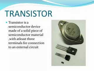
The DC Operation Point HOW A TRANSISTOR CAN BE BIASED? A transistor is biased either with the help of battery or associating a circuit with the transistor. The later method is more efficient and is frequently used. The circuit used for transistor biasing is called the biasing circuit. • Various Biasing Circuits • Fixed Bias Circuit emitter-feedback bias circuit • Fixed Bias with Emitter Resistor Potential Divider Bias Circuit • Collector to Base Bias Circuit
The DC Operation Point Figure 2 Variations in collector current and collector-to-emitter voltage as a result of a variation in base current.
The DC Operation Point Assume a sinusoidal voltage, Vin, is superimposed on VBB, causing the base current to vary sinusoidally 100 mA above and below its Q-point value of 300 mA. This causes the collector current (IC) to vary 10 mA above and below its Q- point value of 30 mA. As a result, the collector-to-emitter voltage varies 2.2 V above and below its Q-point value of 3.4 V. Point A on the load line corresponds to the positive peak of the sinusoidal input voltage. Point B corresponds to the negative peak, and point Q corresponds to the zero value of the sine wave. VCEQ, ICQ, and IBQ are dc Q-point values with no input sinusoidal voltage applied.
Waveform Distortion: Figure 3 Graphical load line illustration of a transistor being driven into saturation and/or cutoff.
Waveform Distortion ((cont’d)) Under certain input signal conditions, the location of Q-point on the load line cause one peak of the load line can cause one peak of the Vce waveform to be limited or clipped, as shown in Figure 5.3(a) and (b). In each case, the input signal is too large for the Q-point location and is driving the transistor into cutoff or saturation during a portion of the input cycle. When both peaks are limited, the transistor is being driven into both saturation and cutoff by an excessively large input signal.
Example 1 Example 1: Determine the Q-point and find the maximum peak value of the base current for linear operation. Assume βDC = 200. Figure 4 For Example 1.
Example 1 (cont’d) Solution:
Base Bias (fixed bias) Circuit recognition: A single resistor (RB) between the base terminal and VCC. No emitter resistor. Figure 5.6 An npn transistor with base bias.
(Base Bias or fixed bias) (cont’d) The analysis of this circuit for the linear region is as follow.
Q-Point Stability of Base Bias: In the last equation, IC is dependent on βDC. The disadvantage of this is that βDC varies with temperature and collector current. The variation in βDC causes IC and VCE to change, thus changing the Q-point of the transistor. This makes the base bias circuit extremely beta-dependent and very unstable.
Collector-Feedback Bias Figure 12 Collector-feedback bias.
Collector-Feedback Bias (cont’d) Applying KVL: