Download
1 / 17
180 likes | 450 Views
Flip-Flop 설계. Contents. Latch vs. Flip-Flop(FF) DFF Synchronous reset vs. Asynchronous reset Enable Signal vs. variable 실습내용 Circular shifter Logical shifter Arithmetic shifter. Latch vs. Flip-Flop(FF). Latch Asynchronous( 비동기 ) 입력에 의해 출력이 변화하는 기억소자

E N D
Contents • Latch vs. Flip-Flop(FF) • DFF • Synchronous reset vs. Asynchronous reset • Enable • Signal vs. variable • 실습내용 • Circular shifter • Logical shifter • Arithmetic shifter
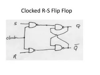
Latch vs. Flip-Flop(FF) • Latch • Asynchronous(비동기) • 입력에 의해 출력이 변화하는 기억소자 • RS latch, Level-sensitive RS latch, JK latch • Flip-Flop(FF) • Clock을 사용 • 클럭에 따라 출력이 변화하는 기억소자 • 초기화를 위한 동기/비동기 입력이 있을 수 있음(reset) • RSFF, DFF, JKFF, TFF clk d_in d_out(F/F) d_out(latch)
DFF • 클럭 입력의 변화에 따라서 D가 Q로 천이 • 클럭의 상승에지(rising edge or positive edge) 또는 하강에지(falling edge or negative edge)에서 천이함 • Reset과 enable 필요 Reset’ D Q Q’ Enable’
DFF • Module entity dff is port( clk, reset, enable : instd_logic; d : instd_logic; q, q_b: outstd_logic ); end entity dff; architecture Behavioral of dff is signal in_q : std_logic; begin q <= in_q; q_b <= not in_q; process( clk, reset) begin if( reset = '0' ) then in_q <= '0'; elsif( clk = '1' and clk'event ) then if( enable = ‘1' ) then in_q <= d; end if; end if; end process; end architecture Behavioral;
DFF • Simulation 결과
Synchronous vs. Asynchronous Reset • Synchronous reset • 입력 클럭이 변화할 때 작동 • Asynchronous reset • 입력클럭과는 상관없이 작동 process( clk ) begin if( clk = '1' and clk'event ) then if( reset = '0' ) then in_q <= '0'; elsif( enable = '0' ) then … process( clk, reset ) begin if( reset = '0' ) then in_q <= '0'; elsif( clk = '1' and clk'event ) then if( enable = '0' ) then …
Enable • Synchronous enable elsif( clk = '1' and clk'event ) then if( enable = '0' ) then in_q <= '1'; else in_q <= d; end if; …
Signal vs. Variable • process(clk) • variable a : std_logic; • begin • if clk’event and clk=‘1’ then • ifrst_n = ‘0’ then • d_out <= ‘0’; • elsif load = ‘1’ then • d_out <= d_in; • a := d_out; • end if; • if a = ‘1’ then • state <= “0001”; • else • state <= “1111”; • end if; • end if; • end process; • process(clk) • begin • if clk’event and clk=‘1’ then • ifrst_n = ‘0’ then • d_out <= ‘0’; • elsif load = ‘1’ then • d_out <= d_in; • sig <= d_out; • end if; • if sig = ‘1’ then • state <= “0001”; • else • state <= “1111”; • end if; • end if; • end process; Ex.) 9
Shift register • 2진 데이터 저장 • 클럭이 인가될 때 왼쪽 혹은 오른쪽 방향으로 데이터 쉬프트
Circular shift • 쉬프트 연산시 최상위 혹은 최하위 비트를 버리지 않고 순환하여 최하위 혹은 최상위로 보내는 쉬프트 • 오른쪽 쉬프트 연산 • 최하위 비트가 최상위로 이동 • 왼쪽 쉬프트 연산 • 최상위 비트가 최하위로 이동 수행전 수행후 b0 b3 b3 b2 b1 b2 b1 b0 수행전 수행후 b3 b2 b1 b0 b2 b1 b0 b3
Logical shift • 쉬프트 연산시 최상위 혹은 최하위 비트를 0으로 함 • 오른쪽 쉬프트 연산 • 최하위 비트가 최상위로 이동 • 왼쪽 쉬프트 연산 • 최상위 비트가 최하위로 이동 수행전 수행후 b3 b2 b1 b0 0 b3 b2 b1 수행전 수행후 b3 b2 b1 b0 b2 b1 b0 0
Arithmetic shift • 쉬프트 연산시 부호비트를 유지하면서 쉬프트 • 오른쪽 쉬프트 연산 • 양수 일 때 부호 비트는 0으로 유지/음수일 때 부호 비트는 1로 유지 • 왼쪽 쉬프트 연산 • Logical shift 연산의 왼쪽 쉬프트와 같음 • 예) 1101 = -3, 왼쪽 산술쉬프트시 1010=-6, 오른쪽 산술쉬프트시 1110=-2 수행전 수행후 b3 b2 b1 b0 b3 b3 b2 b1 수행전 수행후 b3 b2 b1 b0 b2 b1 b0 0
Shift register • 실습내용 • Mode 입력에 따른 Circular, Logical, Arithmetic shifter 설계 • 비동기 Reset 및 동기 enable에 의한 동작 제어
Shift register • Entity entity shifter is port( clk, reset, enable, dir : instd_logic; mode : instd_logic_vector( 1 downto 0 ); pi : instd_logic_vector( 3 downto 0 ); q : outstd_logic_vector( 3 downto 0 ) ); end entity shifter;
Shift register • Simulation 결과
Shift register • 주어진 entity를 사용할 것 • Clock 주기는 10 ns로 할 것 • Testbench는 다음을 따를 것 wait for 103 ns; pi <= “1010”; enable <= '1'; wait for 50 ns; reset <= '1'; enable <= '0'; wait for 60 ns; enable <= '1'; wait for 100 ns; pi <= "1011"; wait for 40 ns; mode <= "01"; wait for 40 ns; enable <= '0'; wait for 20 ns; enable <= '1'; wait for 20 ns; dir <= '1'; wait for 40 ns; mode <= "10"; dir <= '0'; wait for 20 ns; dir <= '1'; wait for 20 ns; mode <= "00"; pi <= "1010"; wait for 20 ns; mode <= "11"; dir <= '0'; wait for 20 ns; dir <= '1'; wait for 20 ns; reset <= '0';