Download
1 / 35
350 likes | 505 Views
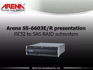
Speaker: Nelson Cheng. Virtual OS Application Arena Redundant RAID. April, 2009. Agenda. Introduction Definition of Virtualization, Market Place, and Methods. Product Detail Redundant System, Fiber Channel Topology and JBOD, System Detail and Features. Live Demo

E N D
Speaker: Nelson Cheng Virtual OS ApplicationArena Redundant RAID April, 2009
Agenda • Introduction • Definition of Virtualization, Market Place, and Methods. • Product Detail • Redundant System, Fiber Channel Topology and JBOD, System Detail and Features. • Live Demo • How VMware works with Arena’s storage. • Question & Answer
Sales Engineer Marketing Application OS Microsoft Linux Mac 7% utilization 6% utilization 14% utilization by all User Application OS Sales / Engineer / Marketing Microsoft / Linux / Mac 28% utilization Why Need Virtualization? • Utilization includes: • CPU • Memory • Disk Space (or Storage Space) • Network • Add factors: • Infrastructure Management • Support Effort • Eliminate factors: • Equipment Spending • (Cost = Money $$..a big factor • Repeat OS Installation and Configuration • Tools & Application Share Ability
Channel (Link) Virtualization Storage Virtualization What Is Virtualization? • Abstraction of Computer Resources • CPUs, Memory, Storage, Network • Server, Channel and Storage Virtualization • Advantages • Consolidation, increase hardware utilization, • transparent for user flexibility • Disadvantages • Depending on application: performance losses • Two Server Virtualization Methods • Para virtualization & Full virtualization • Hypervisor • VMWare, Hyper-V, and Xen ….etc. Server Virtualization
PARAVIRTUALIZATION Linux Windows Mgt Code Device Driver Mgt API Windows Hardware API User Apps User Apps Intel VT Hardware AMD Pacifica Virtual Machines App App App OS OS OS ESX Server Two Server Virtualization Method • Para virtualization –Each guest operating system has special drivers to access the host or storage operating system (ex. Traditional Xen [Citrix], Logical Domains [SPARC]) Full virtualization –All hardware is simulated by the host operating system, guest operating system can be unchanged (ex. VMware) 5
Channel (Link) Virtualization • Channel Virtualization is usually exist in Fiber or maybe iSCSI, but not in SAS...etc. • Channel Virtualization (ex. Fiber) provide traffic prioritization by different link-level quality of service (QoS) • Channel Virtualization provides better link bandwidth utilization • Channel Virtualization provides congestion management by bandwidth allocation • Fiber channel virtualization improves the disk utilization, and also it simplifies the implementation of Zoning and LUN Masking Volume A Zone 1 Host 1 Volume B Host 2 Zone 2 Volume C Disks Switch Servers 6
Redundant FC SS-8801R JBOD SS-6692R VMware SuSe 10 Virtual Center SASSS-6652E Windows XP / 2003 VMware VMware JBOD SS-6692J FCSS-6651E ESX 3.5 Windows Vista / 2008 iSCSISS-6603S Linux redhat 4.0/5.0 DB Oracle SAP MS-SQL MySQL Redundant SAS SS-6602R ․ ․ ․ Redundant SS-8801R SuSe 10 SP1, SP2 JBOD SS-6692R Windows 2008 64-based Editions Windows XP / 2003 SASSS-6652E Hyper-V Hyper-V Windows Vista / 2008 JBOD SS-6692J FCSS-6651E Linux redhat 4.0/5.0 iSCSISS-6603S ․ ․ ․ Storage Virtualization_VMware / HyperV
Why Storage Controller Redundant ? • Current storage design used by RAID technique, data is kept safely without question. However, within one system, power supply and fan are normally with its redundant design, so why not the controller itself? • Once one of the controllers accidentally failed, the survival controller can quickly pick up the unfinished tasks and continue. • In a redundant system from its independent mode, two controllers can work together to gain a better performance or they can work separately within its associated input or output without other interruption.
Device Mapper Kernel User space Lib dev mapper dm setup LVM 2 Multipath EVMS Redundant System Overview • Active-active redundant operation. Mechanism needs host intervention. • The MPIO driver is essential to achieve the no-data-loss goal while single controller failure. • Failover incurs path failover guided by MPIO driver. • Login in one of the controllers and can finish all needed configurations across the two controllers, which includes Volume Disk creation or deletion, storage presentation, and maintenance, etc.
Redundant System Overview • Maxtronic redundant system design extends the no-single-point-failure to the controller entity. • Two controllers in one system. They are named by controller A (left/top), and controller B (right/bottom). • A full-duplex RCC (redundant communication channel) is established for synchronization purpose. • - Configuration • - Object state • - Write cache • The write-cache data is preserved only when one of the controller is failed. Cache Coherence Channels Controller A Controller B
Controller Overview • High Speed BP Melt • Hot swappable redundant controller • Support up to 24 drives in one enclosure • On Board SAS Expander • Flexible to support from 12-bay, 16-bay, and 24-bay • Cache coherence • X4 full-duplex SAS for cache coherence Intel XScale IOP341 • PCI Express X 8 • Up to 2000 MB/s • transfer rate • DDR2-533 Cache Memory • ECC and BBM protected • Up to 4GB memory size • Host Interface Daughter board • To support SAS, iSCSI, PCI-e, and FC • Expansion Port • Cascade external SAS JBOD • Support SAS expansion, up to 128 SAS devices • Dual 4Gbps Fibre Channel • Up to 800 MB/s transfer rate • To support quad 4G FC ports • Phone Jack • Communication with host COM port • On-board Ethernet Port • Embedded web server with GUI • Remote centralized management
Daughter Board Overview • LSI1064e • PCI-e to 3Gb SAS high speed IO controller • PMC DE4 • PCI-e to 4Gb FC high speed IO controller • Dual 4Gbps Fibre Channel • Up to 800 MB/s transfer rate • To support quad 4Gb FC ports • Dual X4 Wide port SAS Channel • Up to 2400 MB/s transfer rate • To support quad 12 Gb SAS ports
Redundant System View 24-bay Redundant Chassis LCD Panel Key Lock Up, Down, Enter, Esc button Fan 1 Fan 3 Fan 4 Fan 2 Controller B Controller A Power Supply 1 Power Supply 3 Power Supply 2
Management Interface (GUI) Online Help Environment Control Front View Rear View Logon Prompt Version
Logical Volume (LV) How Linux Is Associated With? Linux LVM Objects Volume Group (VG) Storage Layer Objects Logical Volume (LV) Logical Disks (LD) Physical Extent (PE) Disk Groups (DG) /dev/hda1 /dev/hdb1 /dev/hdc1 Physical hard disks Physical Volume (PV)
Redundant Expansion Topology SS-8801R, SS-6601R, SS-4501R, SS-8802R, SS-6602R SS-8892R, SS-6692R * Please note that there are some empty slots shown in the SAS JBOD enclosure display (in the last enclosure tab) due to the maximum number of supported drives.
Fiber Channel Topology-I Fabric Loop N _Port N _Port N _Port L _Port L _Port L _Port L _Port N _Port Fabric N _Port L _Port L _Port N _Port N _Port N _Port L _Port Point_to_Point N _Port N _Port
Fiber Channel Topology-II Host port of Controller B Host port of Controller A Heart beat Link Dual host Non-clustering env. Single host Redundant Disk Array Redundant Disk Array Dual host Clustering env. with paths exchange Dual host Clustering env. Without paths exchange Redundant Disk Array Redundant Disk Array
Host port of Controller B Host port of Controller A Expansion port of JBOD Fiber Channel Topology-III - thru Switch - Windows Server or Linux Server SUN Solaris SPARC Server Fibre Switch Redundant Disk Array Mac OS X Server JBOD Redundant Disk Array JBOD JBOD
No Single-Point-Of-Failure Design Redundancy in all hardware components ensures no single point of failure and system availability Minimized System Degradation Proactive data protection prevents system from entering degradation, offering not only 365x24x7 on-line but also optimal Features Highlight Dual Active-Active Controller Snapshot ready support Non-interruptive FW upgrade Fail-over / Fail-back Multiple I/O Path Online Array Recovery
MPIO Driver Installed MPIO Installation Procedure Setup Path Guard utility After its installation is completed, rebootthe host OS. Start to Install MPIO Installer Verify if or "vender name_model name" Click "Next" to start installation. After installed reboot the OS Start MPIO GUI
Failover and Failback • Failover (FO)- it’s kind of system redundant ability when one of the controllers (paths) is unworkable, the other survival controller (path) will take over the failed job and keep the host operation normally. • Failback (FB) - as a system is in the controller or path failover mode, and the host detects a healthy controller or path has been replaced the original failures one, then the system will go into the controller or path failback mode, finally, the survival controller or path will return the failed controller or path job to the original controller or path. • Arena's redundant controller system is support two FO and FB modes- “Controller FO/FB Mode” and “Path FO/FB Mode”.
Controller Failover and Failback Host with MPIO driver installed A B B Controller failover LD 1 LD 1 LD 2 LD 2 Controller failback Active path to LD 2 Active path to LD 1 Standby path to LD 2 Standby path to LD 1
Path Failover and Failback Host with MPIO driver installed A A B B Path failover LD 1 LD 1 Path failback LD 2 LD 2 Active path to LD 2 Active path to LD 1 Standby path to LD 2 Standby path to LD 1
FC Switch LUN A A1 Volume A Volume A LUN A Loop 1 LUN C A2 Volume B Volume B LUN B Host Computer without MPIO Controllers FC Switch Volume C LUN A Volume C A1 Volume A Volume A B1 LUN B LUN C LUN A Loop 1 LUN C A2 B1 LUN B Volume B Volume B Loop 2 Volume D B2 LUN D LUN B Volume D LUN D Volume C Volume C LUN C LUN B Loop 2 Volume D B2 LUN D Volume D LUN D LUN D Controller MTID based FO & FB
Data Synchronization • Configuration Data • Both Controller’s configurations and states are synchronized between two controllers. • Event Logs • The event logs are mirrored between controllers so that users can view the event logs even if one of the controllers is failed. • Task Progress Data • A controller’s background task data will be synchronized to the peer controller. If one the two fails then the survival will resume the jobs. • Task Progress Data • RTC will be synced between two controllers in a fixed period of time. 27
Non-interruptive Firmware Update Update from Controller A Firmware or Boot code Controller A Cache Coherence Channels Controller B Receive by Controller B and update 28
Demonstration Flow Add Storage Provide store name & file system format Log onto VMware Infrastructure Client Check ESX server’s summary, VM, performance, and configuration. Repeat steps Create storage identification Enable all virtual machinesOS Select Storage Adapter check device is attached. Edit settingfrom VM Add data store with disk size Power onthe VM Consolemode, check virtual disk and Finish
a more powerful way for storage a more powerful way for storage