Download
1 / 7
70 likes | 200 Views
System Hardware. FPU – Floating Point Unit Handles floating point and extended integer calculations 8284/82C284 Clock Generator (clock) Synchronizes the CPU and the rest of the computer 8259 Programmable Interrupt Controller (PIC)

E N D
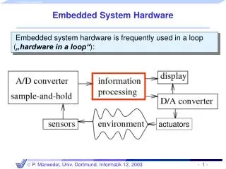
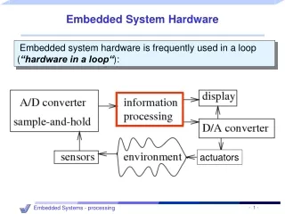
System Hardware • FPU – Floating Point Unit • Handles floating point and extended integer calculations • 8284/82C284 Clock Generator (clock) • Synchronizes the CPU and the rest of the computer • 8259 Programmable Interrupt Controller(PIC) • Handles external interrupts from hardware devices (keyboard, system clock, disk drives, etc…) • 8253 Programmable Interval Timer/Counter • Interrupts the system 18.2 times per second. Updates system date and clock, controls the speaker. Also responsible for constantly refreshing memory
The CPU • Registers (Data, Address, Flags) • Buses (Data, Address, Control • Clock • ALU • Control Unit(CU)
Instruction Cycle • The amount of time taken to complete the three basic steps: • ·Fetch: the CU fetches an instruction, copying it from memory into the CPU • ·Decode: The CU increments the program counter and decodes the instruction. If other operands are specified by the instruction, the CU decodes their addresses and fetches the operands. The CU passes the instruction and operands to the ALU via the prefetch queue which acts as a waiting area for the ALU. • ·Execute: The ALU executes the operation and passes the result operands to the CU, where they are returned to registers and memory. • Each step in the instruction cycle takes at least one tick of the system clock, called a clock cycle.
Calculating Instruction Timings • In many applications, choosing the most efficient way to code a group of instructions is required (data communications, real-time processing). Factors include: • · CPU • · Clock Speed of CPU • · Instruction mnemonic • · Addressing mode • To measure the speed of an instruction: • · # of clock cycles required to execute it • · speed of the CPU’s internal clock
INC Instruction Timings in Clock Cycles Operand Type 88/86 286 386 486 reg16 3 2 2 1 mem16 23+EA 7 6 3 EA: Effective address – the time it takes for the processor to calculate various addressing modes. (EA calculation is NOT a factor from the 286 onward. It is done at the hardware level, so there is no difference in execution speed between a direct operand and a base-indexed operand). Example – For a 33MHz 386 processor: (2 clock cycles for INC instruction)/33000000) = 0.00000006 sec (60nsec) Note: This does not take into consideration parallel execution of instructions.
Reading From memory • An important factor when understanding the speed of a program • If CPU runs at 200MHz, RAM runs at 66MHz, there will usually be some waiting on the part of the CPU while operands are fetched from memory • High-speed level-2 cache that holds most recently used instructions and data
CPU Instruction Cycle • T1 – address of memory operand placed on address bus. Done by CPU setting correct address pins high or low • T2 – Read line (RD) is set low to notify memory that a value is to be read • T3 – CPU waits for memory to respond • T4 – Read Line (RD) goes to 1, signaling that the CPU can now read the values on the data bus.


![1.6 Inside the system unit [Hardware]](https://cdn2.slideserve.com/4878996/1-6-inside-the-system-unit-hardware-dt.jpg)