Download

1 / 21
220 likes | 342 Views
ALIBAVA system hardware. 15th RD50 Workshop, 16-19 November 2009, CERN. Ricardo Marco-Hernández. IFIC(CSIC-Universidad de Valencia) 1. ALIBAVA system hardware. Marco-Hernández, R. a , On behalf the ALIBAVA Collaboration b

E N D
ALIBAVA system hardware 15th RD50 Workshop, 16-19 November 2009, CERN Ricardo Marco-Hernández IFIC(CSIC-Universidad de Valencia) 1 ALIBAVA system hardware Marco-Hernández, R.a, On behalf the ALIBAVA Collaboration b a Instituto de Física Corpuscular (IFIC), Universidad de Valencia-CSIC,Valencia, Spain. b Department of Physics, Oliver Lodge Laboratory, University of Liverpool, Liverpool, UK. Instituto de Microelectrónica de Barcelona, IMB-CNM, CSIC, Barcelona, Spain. Instituto de Física Corpuscular (IFIC), Universidad de Valencia-CSIC,Valencia, Spain.
ALIBAVA system hardware 15th RD50 Workshop, 16-19 November 2009, CERN ALIBAVA Ricardo Marco-Hernández IFIC(CSIC-Universidad de Valencia) 2 Outline • Main system characteristics. • System architecture. • Daughter board. • Mother board. • Hardware/Firmware/Software Updates. • Summary.
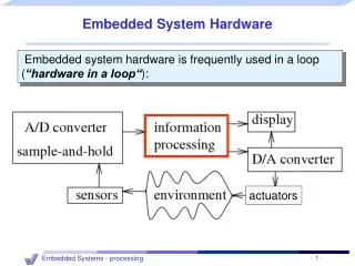
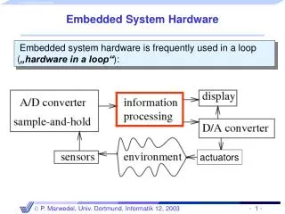
ALIBAVA system hardware 15th RD50 Workshop, 16-19 November 2009, CERN Ricardo Marco-Hernández IFIC(CSIC-Universidad de Valencia) 3 Main system characteristics • A compact and portable system. • The system can be used with two different laboratory setups: • Radioactive source: external trigger input from one or two photomultipliers. • Laser system: synchronized trigger output generated internally for pulsing an external excitation source. • The system contains two front-end readout chips (Beetle chip used in LHCb) to acquire the detector signals. • USB communication with a PC which will store and will process the data acquired. • System control from a PC software application in communication with a FPGA which will interpret and will execute the orders. • Own supply system from AC mains. The main goal is reconstructing the analogue pulse shape from the readout chip front-end with the highest fidelity from the acquired data.
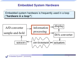
ALIBAVA system hardware 15th RD50 Workshop, 16-19 November 2009, CERN Ricardo Marco-Hernández IFIC(CSIC-Universidad de Valencia) 4 System architecture • Software part (PC) and hardware part connected by USB. • Hardware part: a dual board based system connected by flat cable. • Mother board intended: • To process the analogue data that comes from the readout chips. • To process the trigger input signal in case of radioactive source setup or to generate a trigger signal if a laser setup is used. • To control the hardware part. • To communicate with a PC via USB. • Daughter board : • It is a small board. • It contains two Beetle readout chips. • It has fan-ins and detector support to interface the sensors. • Software part: • It controls the whole system (configuration, calibration and acquisition). • It generates an output file for further data processing.
ALIBAVA system hardware 15th RD50 Workshop, 16-19 November 2009, CERN Ricardo Marco-Hernández IFIC(CSIC-Universidad de Valencia) 5 Daughter board • Two Beetle readout chips in parallel mode (256 input channels). • Buffer stage for Beetle analogue output signals. • Differential current to differential voltage buffer. • Buffered signals with impedance matched. • Fast control (LVDS signals) and slow control (I2C bus) shared by Beetle chips. • A thermistor (NTC) for sensing the temperature close the Beetle chips. • Low voltage DC level (5 V) for Beetle chips (2.5 V) and buffer stage power supply (4.5 V): provided by the motherboard and regulated on board. • High voltage DC level for silicon detector(s) bias: external power supply filtered on board. • Fan-ins and detector board: detector connection by multiple wire bonding.
ALIBAVA system hardware 15th RD50 Workshop, 16-19 November 2009, CERN Ricardo Marco-Hernández IFIC(CSIC-Universidad de Valencia) 6 Beetle chip • Readout chip developed at ASIC laboratory of the University of Heildelberg. • 128 input channels. • Analogue front-end with charge amplifier, shaper and charge injection circuitry (calibration). • Vp = kQ. Tp ~ 25 ns. Total pulse length about 65-70 ns. • Analogue signal is sampled into the analogue pipeline (128x187 cells) with the frequency of the Beetle chip clock (40 MHz). • The analogue pipeline programmable latency fixed to 128 CLK cycles (3.2 µs). • Fast control signals (LVDS): Rst, Clk, Trigger and Testpulse. • Slow control (I2C) for chip configuration.
ALIBAVA system hardware 15th RD50 Workshop, 16-19 November 2009, CERN Ricardo Marco-Hernández IFIC(CSIC-Universidad de Valencia) 7 Beetle chip (II) • Readout from a Trigger pulse: 128 channels serialized from a pipeline column. • Analogue output format: single readout onto one output. • Readout: 16 bits header + 128 analogue multiplexed channels. • Channel width of 25 ns (40 MHz clock). • DataValid signal for readout detection. • Output dynamic range: linear up to ~ ±110000 e-.
ALIBAVA system hardware 15th RD50 Workshop, 16-19 November 2009, CERN Ricardo Marco-Hernández IFIC(CSIC-Universidad de Valencia) 8 Daughter board: detector support • Fan-ins: • Three fan-ins: chip fan-in, intermediate fan-in and detector fan-in. • Each fan-in has pads of 80 um pitch and 10 rows for multiple wire bonding. • A new fan-in of 256 channels have been designed. • Detector board: • Accomodates the detector fan-in(s) and the sensor(s). • There are various detector board versions for different sensor sizes. • Small, for 1cm2 sensors (board dimensions ~37mm x 32mm). • Large, for 1cm x 3cm sensors (board dimensions ~37mm x 50mm). • Test-box: • Daughter board and detector boards are fixed to base plate for facilitating wire-bonding.
ALIBAVA system hardware 15th RD50 Workshop, 16-19 November 2009, CERN Ricardo Marco-Hernández IFIC(CSIC-Universidad de Valencia) 9 Mother board: signal conditioning and ADC • Signal conditioning block transforms the differential voltage analogue input signal from each Beetle to: • Drive an oscilloscope: single ended signal. • Drive ADC: differential input shifted signal. • ADC (one for each Beetle): • 10 bit flash type with a sample rate of 40 MHz. • Nominal resolution of 1 mV (output signed code, 9 bits plus 1 sign bit). • Dynamic range: ±1024 mV.
ALIBAVA system hardware 15th RD50 Workshop, 16-19 November 2009, CERN Ricardo Marco-Hernández IFIC(CSIC-Universidad de Valencia) 10 Mother board: trigger inputs • In case of radioactive source setup for obtaining a time stamp of each trigger. • Trigger conditioning: • Leading-edge discrimination for two photomultiplier analogue input signals. • Level conversion for an auxiliary signal (current or voltage). • Two dual LVPECL high speed comparators. • Four programmable voltage thresholds: generated with a quad 12 bits DAC. • TDC: measurement of t between input trigger and a reference signal. • A TDC integrated circuit (TDC-GP1). • Nominal resolution: 600 ps. • 100 ns dynamic range.
ALIBAVA system hardware 15th RD50 Workshop, 16-19 November 2009, CERN Programmable delay Ricardo Marco-Hernández IFIC(CSIC-Universidad de Valencia) 11 Mother board: trigger output • In case of laser setup. • A synchronised trigger signal (TRIG OUT) is generated to drive a laser source to reconstruct the Beetle front-end pulse shape. • Programmable delay circuit (3D7428): • Resolution: 1 ns. • Range: up to 255 ns. • Programmed by FPGA by serial interface. • Following this block a 50 Ω driver has been incorporated for driving a pulse generator input.
ALIBAVA system hardware 15th RD50 Workshop, 16-19 November 2009, CERN Ricardo Marco-Hernández IFIC(CSIC-Universidad de Valencia) 12 Mother board: other blocks • SDRAM (256 Mb): for acquisition data storage. • TEMPERATURE CONVERTER: NTC thermistor signal digitalization. • SLOW CONTROL: generated directly by the FPGA. External pull-up resistors for SDA and SCL lines. • FAST CONTROL: • LVDS driver (DS90LV47A) and LVDS receiver (DS90LV48A). • Six CM noise suppressor chokes (23Z105SM). • USB: USB controller (FT245R) for USB to FIFO parallel (8 bits) bidirectional data transfer. • SUPPLY SYSTEM: • DC input (5V) from AC adapter. • Digital levels from 2 DC-DC converter (1.2 V and 3.3 V) + 1 linear regulator (2.5 V). • Analogue levels from DC-DC converter (±5V) + 1 linear regulator (3.3V). • Daughter board level from DC-DC converter (5V).
ALIBAVA system hardware 15th RD50 Workshop, 16-19 November 2009, CERN Ricardo Marco-Hernández IFIC(CSIC-Universidad de Valencia) 13 Mother board: FPGA logic • FPGA hardware: • Xilinx Spartan-3 (XS3400-PQ208) clocked at 40 MHz. • External reset push button. • On-system configuration PROM memory. • Two LEDs for system status. • FPGA logic operation: • Custom logic blocks (VHDL) for low level hardware control. • Centralized control from a CFSM. • FPGA logic blocks: • A CFSM (Central Finite State Machine) will control the different blocks depending on the current state of the system. • Radioactive source: the DAC CONTROL, TRIGGER IN and TDC CONTROL will be used for processing the trigger inputs and obtaining a time stamp of each trigger. • Laser setup: the TRIGGER OUT block will generate the output trigger signal and will control the programmable delay circuit.
ALIBAVA system hardware 15th RD50 Workshop, 16-19 November 2009, CERN Ricardo Marco-Hernández IFIC(CSIC-Universidad de Valencia) 14 Mother board: FPGA logic • FPGA logic blocks: • ADC CONTROL: readout of the digitized data frames when the input DataValid (fast control) signal will be active. This digitized data will be stored in an internal FIFO RAM. • BEETLE FAST CONTROL: generation of fast control signals (Clk, Trigger, Testpulse and Reset) depending on the state of the system. • BEETLE SLOW CONTROL: I2C master controller for writing/reading the Beetle internal registers for chip configuration. • SDRAM CONTROL: implements a controller for interfacing the SDRAM and the CFSM. • USB CONTROL: interface between the USB controller and the CFSM. • CLOCK GENERATOR: required internal clock and reset signals generation.
ALIBAVA system hardware 15th RD50 Workshop, 16-19 November 2009, CERN Ricardo Marco-Hernández IFIC(CSIC-Universidad de Valencia) 15 Mother board: FPGA logic • FPGA logic: • The CFSM and SDRAM CONTROL have been implemented with an embedded system (soft processor + SDRAM peripheral). • Soft processor: Microblaze (32 bits RISC) at 40 MHz. • SDRAM controller included as standard peripheral for the Microblaze. • ARBITRER : custom block of registers for communication between the embedded processor and the custom logic blocks. • FSLs (Fast Simplex Links): unidirectional FIFOs for fast communication between the ARBITRER and the Microblaze. • The functionality of the system is programmed as a standard C program in the processor (firmware): great flexibility for changes.
ALIBAVA system hardware 15th RD50 Workshop, 16-19 November 2009, CERN Ricardo Marco-Hernández IFIC(CSIC-Universidad de Valencia) 16 Hardware/Firmware/Software Updates • Hardware Update: daughter board linear regulator replacement. • 3V LDO by 4.5V LDO. • Increase common mode input range at the buffer stage. • Gain behaviour of the system at low T is improved. • Proposed firmware/software update: calibration delay scan. • Delay between Trigger and Testpulse LVDS signals configurable by the user. • The aim is to reconstruct the analogue pulse at calibration stage. • In 1 ns steps and with a 100-150 ns range (full pulse width). • FPGA firmware and software changes. • Thanks to Michel Walz (Uni. Freiburg) and Tony Affolder (Uni. Liverpool).
ALIBAVA system hardware 15th RD50 Workshop, 16-19 November 2009, CERN Ricardo Marco-Hernández IFIC(CSIC-Universidad de Valencia) 17 Summary • The readout system has been developed and is fully operational. • The system can operate with different types and different sizes of microstrip detectors: • n-type. • p-type. • Irradiated and non-irradiated. • Up to 256 input channels. • The system has been designed to operate with a radioactive source setup and a laser setup. • The system has been distributed among RD50 Collaboration members and to other institutions. • Feedback received from first users: proposed hardware/firmware/software updates. • Do not forget to check the twiki of the ALIBAVA system (https://twiki.ific.uv.es/twiki/bin/view/Atlas/ALiBaVa) for updated info. • Future work: • Upgrade of the system for testbeam acquisition. • Synchronization of 5 MBs.
ALIBAVA system hardware 15th RD50 Workshop, 16-19 November 2009, CERN Ricardo Marco-Hernández IFIC(CSIC-Universidad de Valencia) 18 ALIBAVA system hardware Marco-Hernández, R.a, On behalf the ALIBAVA Collaboration b a Instituto de Física Corpuscular (IFIC), Universidad de Valencia-CSIC,Valencia, Spain. b Department of Physics, Oliver Lodge Laboratory, University of Liverpool, Liverpool, UK. Instituto de Microelectrónica de Barcelona, IMB-CNM, CSIC, Barcelona, Spain. Instituto de Física Corpuscular (IFIC), Universidad de Valencia-CSIC,Valencia, Spain.
ALIBAVA system hardware 15th RD50 Workshop, 16-19 November 2009, CERN Ricardo Marco-Hernández IFIC(CSIC-Universidad de Valencia) 19 PC software • Functions: • Control the whole system (configuration, calibration and acquisition). • Processing and monitoring of acquired data. • User interface with the system (GUI). • Generation of information (output files). • Two software levels: • Low level: • Software/mother board communication by USB: VCP (virtual com port) driver (2.4 Mb/s) used. • Processing of acquired data. • High level: • GUI: control of the system and data monitoring. • Output file generation for further processing and analysis. • Programmed in C++. • Operating system compatibility: • Linux version fully operational. • Maybe Windows in the future. • There are also macros for ROOT in order to process the data acquired with the software.
ALIBAVA system hardware 15th RD50 Workshop, 16-19 November 2009, CERN Ricardo Marco-Hernández IFIC(CSIC-Universidad de Valencia) 20 Mother board: system operation • RESET: • System initialization. • With a power on, with an external reset or by software reset. • WAITING: • The system waits for an order coming from the PC software to go to another state. • BEETLE CONFIGURATION: • Beetle chips configuration registers programming. • CALIBRATION: • System calibration by the Beetle internal test pulse generator. • Known amplitude readouts are acquired. • TRIGGER IN CONFIGURATION: • DAC voltage thresholds are programmed. • Trigger inputs scheme is configured. • LASER SYHRONIZATION: • The system is synchronized for the Beetle front end pulse reconstruction. • By delaying the TRIG OUT signal in 1 ns steps.
ALIBAVA system hardware 15th RD50 Workshop, 16-19 November 2009, CERN Ricardo Marco-Hernández IFIC(CSIC-Universidad de Valencia) 21 Mother board: system operation • PEDESTALS, RS or LASER ACQUISITION: • A programmable number of readouts can be acquired (up to 64776) and stored in the SDRAM. • PEDESTALS: For each event a Beetle chips readout (256 by 16 bits) and a temperature readout are stored in the SDRAM. No charge acquired with Beetle chips. • RS: For each event a Beetle chips readout (256 by 16 bits), a TDC readout (32 bits) and a temperature readout are stored in the SDRAM. • LASER: For each event a Beetle chips readout (256 by 16 bits) and a temperature readout (16 bits) are stored in the SDRAM. The TRIG OUT frequency is fixed to 1 KHz. • PEDESTALS, RS or LASER READING: • The last type of acquisition data are read from SDRAM and data are sent to PC by USB.