Download
1 / 33
340 likes | 453 Views
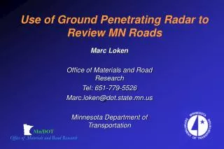
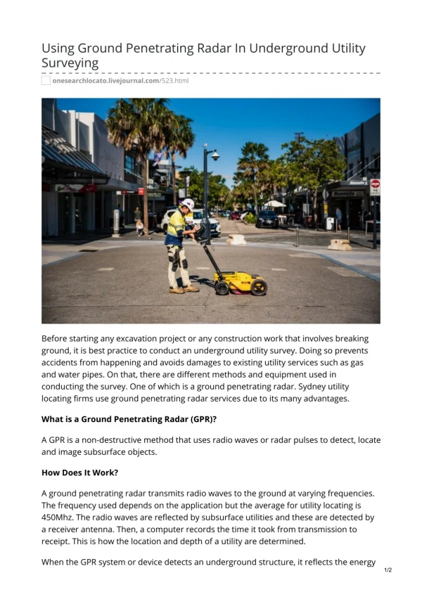
Mn/DOT Office of Materials and Road Research. Use of Ground Penetrating Radar to Review MN Roads. Marc Loken Office of Materials and Road Research Tel: 651-779-5526 Marc.loken@dot.state.mn.us Minnesota Department of Transportation. Outline. Applications of GPR Basic Principles of GPR

E N D
Mn/DOT Office of Materials and Road Research Use of Ground Penetrating Radar to Review MN Roads Marc Loken Office of Materials and Road Research Tel: 651-779-5526 Marc.loken@dot.state.mn.us Minnesota Department of Transportation
Outline • Applications of GPR • Basic Principles of GPR • MnDOT GPR Equipment • Current Projects • Future Projects • Conclusions
Applications of GPR • Determine pavement thickness • Calculate material properties • Detect subsurface anomalies • Determine depth to bedrock • Detect stripping and/or layer separation • Analyze rutting mechanisms • Detect subsurface moisture and/or freezing
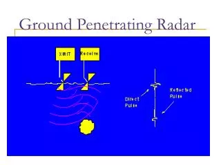
Material Characterization Dielectric Constant The dielectric constant of a material is its ability to store electrical energy
Dielectric Constant Calculation 1= [(1+ρ1)/(1- ρ1)]2 where: 1= dielectric constant of surface layer 1 = A1/ Am A1= amplitude of the surface reflection from the surface layer Am = amplitude of the surface reflection from metal sheet
Calculation of Layer Thickness 2*h1 =c t1 / 1 where: h1 = thickness of 1stlayer c = speed of radar in air = 11.8 in/ns t1= time required to transmit signal through 1st layer
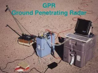
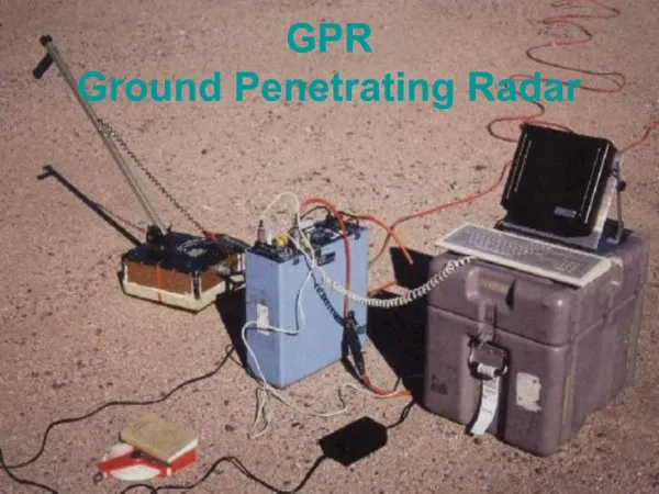
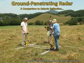
MnDOT GPR Equipment • Data Collection Systems • SIR 2000 • SIR 020 • Antenna • 100 MHz (5 to 20 ft depth) • 400 MHz (2 to 10 ft depth) • 1 GHz (Air-Coupled) (0 to 4 ft depth) • 1.5 GHz (0 to 3 ft depth) • Post-Processing Software • RADAN NT • RoadDoctor (tenatative)
Current Projects • MnROAD – Calibration, Rutting, Layer Thickness, Material Identification • Olmsted CR 117 – Ground Truth Measurements, Layer Thickness • TH 212 – Subsurface Cracks, Pavement Layer Identification • TH 22 – Evaluate Pavement Thickness, Road Structure • TH 7 – Stripping Layers and Interface Separation
MnROAD • Objectives • Calibration • Layer Thickness • Material Identification • Pavement Structure • Cells 33-35 • 4” Asphalt • 12” Class 6 • Cell 36 • 6 1/4” Concrete • 5” Class 5
MnROAD -- Calibration Cell 33
MnROAD – Layer Thickness Cell 34
MnROAD – Material ID Cell 36
Olmsted CR 117 • Objectives • Ground Truth Measurements • Layer Thickness • Pavement Structure • 6” Asphalt • 12” Class 5
Olmsted CR 117 – Layer Thickness Station 130+00
TH 212 • Objectives • Subsurface Cracks • Pavement Layer Identification • Pavement Structure • 9-10” Asphalt • 13-14” Gravel Base • Concrete or Clay Loam Subgrade
TH 212 – Subsurface Cracks Mile 118.4
TH 212 – Clay Loam Mile 118.0
TH 212 – Concrete Mile 118.4
TH 22 • Objectives • Pavement Thickness • Road Structure • Pavement Structure • 3-6” Asphalt • Concrete or Gravel Base
TH 22 – Pavement Thickness Greeley Ave
TH 22 – Material Identification Ford Ave
TH 7 • Objectives • Stripping Layers • Interface Separation • Pavement Structure • 10-12” Asphalt • 12-36” Gravel
TH 7 – Interface Separation Mile 152.6
Future Projects • MnROAD (Rutting Mechanisms) • Pine Co. (Stripping and Overlay History) • St. Louis County (Depth to Bedrock) • TH 55 (Fault Plane Survey) • Interstate Park (Potholes in Bedrock)
Conclusions • GPR is nondestructive field test used to determine road structure • GPR utilizes high-speed data collection at speeds up to 50 mph • Gives a continuous subsurface description • GPR can be used to identify subsurface structures up to 20 ft in depth