Download
1 / 55
640 likes | 1.18k Views
Physics and control of Edge Localized Modes (ELMs). Valentin Igochine. Max-Planck Institut für Plasmaphysik EURATOM-Association D-85748 Garching bei München Germany. Outline. Motivation Physics of ELMs The trigger physics ELM size and filament physics Nonlinear behaviour of ELM

E N D
Physics and control of Edge Localized Modes (ELMs) Valentin Igochine Max-Planck Institut für Plasmaphysik EURATOM-Association D-85748 Garching bei München Germany
Outline • Motivation • Physics of ELMs • The trigger physics • ELM size and filament physics • Nonlinear behaviour of ELM • MHD modelling of ELMs • Control of ELMs • Pellets • Gas puffing • Vertical kicks • Resonant Magnetic Perturbations • Summary
Schematic representation of the ELM cycle Kamiya, PPCF, 2007 ELM crash, ejecting plasma energy/particle towards Scrape-Off-Layer (SOL)
Why is ELM control urgent for ITER? Q = 1.0 MJ/m2 Q = 1.6 MJ/m2 Zhitlukhin JNM 2007 Tungsten Erosion Q = 0.9 MJ/m2 Tungsten melting, droplets, surface cracks if WELM>1MJ. ... but predicted for large ELMs: WELM,ITER~30MJ! (ITER divertor life-time = only few shots with big ELMs!) This requires a decrease in the ‘natural’ ELM size by a factor of ~ 30 ELM suppression/control is required for a steady state operation of ITER!
ELM trigger: ideal MHD • It is widely believed that ideal MHD instabilities provide the trigger for the ELM • Theoretically, the instability properties can be understood from dW for radial displacement, X, at large toroidal mode number, n: Field-line bending: strongly stabilising unless k|| is small Pressure gradient/curvature drive: destabilising if average curvature is “bad” Current density gradient/edge current drives kink/peeling modes s=normalised current density • Must ensure field-aligned perturbations or field line bending will suppress the instability: ideal MHD naturally produces filamentary structures
Kink or peeling modes • A single, resonant Fourier mode Single Fourier mode, highly localised at rational surface eliminates field line bending |X|2 constant around poloidal plane, so experiences “good” average curvature Pressure gradient is stabilising Driven unstable by current gradient at modest n: kink mode Or edge current density at large n: peeling mode • Peeling and kink modes are essentially the same thing • Driven by current density gradient, stabilised by pressure gradient • Highly localised
Ballooning modes • Multiple Fourier modes couple to tap free energy of pressure gradient To couple, each Fourier mode must extend across multiple rational surfaces: Field line bending is minimised, but not eliminated Multiple Fourier modes couple to constructively interfere in bad curvature region: |X|2 is maximum on outboard side Current gradient does not play a role at large n; edge current can influence mode • Ballooning mode is unstable when the curvature exceeds field line bending • Critical dp/dy is required (depends on shear, and therefore current) • Many coupled Fourier modes radially extended mode structure
Ideal MHD stability diagram • The peeling-ballooning mode stability diagram Peeling/kink unstable Current density Ballooning unstable Stable Pressure gradient • Important (slightly subtle) point • Although stability diagrams are shown in terms of local dp/dr and J, profile effects cannot be neglected (when n is finite) • Higher pressure gradient can be achieved for a narrower pedestal care when interpreting experimental pedestal profiles
Ideal MHD stability diagram • Typical ELITE stability diagram (model JET-like equilibrium) Peeling-ballooning mode
Types of ELMs Definitions from Connor, PPCF, 98 L-H transition type I (giant) Most dangerous! ELM size type III (small) ‘dithering’ ELMs ELM-free H-mode Input power type II (or, sometimes, ‘grassy’) are associated with strongly-shaped tokamaks at high edge pressure when there is access to the second stability at the plasma edge
The ELM cycle: TypeI • Initial models: Type I ELM cycle • High pressure gradient in pedestal (so good performance) • Low collisionality, and strong bootstrap current • Extended linear mode across pedestal region • Anticipate a substantial crash Peeling/kink unstable Ballooning unstable
The ELM cycle: Type III • Initial models: Type III ELMs (more speculative?) • Either highly collisional edge, destabilising resistive ballooning, driving pedestal to lower gradient and crossing peeling stability boundary • Or at higher temperatures, higher current pushes pedestal directly across peeling stability boundary • However, data seems to suggest Type III are stable to ideal modes (but uncertainty over edge current) Type I JET Type III Peeling/kink unstable Ballooning unstable L-mode Saarelma, PPCF, 2009
The ELM cycle: Type II • Initial models: Type II ELMs (speculative, again) • Higher collisionality would help to suppress bootstrap current • Strong shaping can also push peeling boundary to high current density • Removes role of peeling mode, providing a pure ballooning mode Peeling/kink unstable Ballooning unstable
ELM Types: experiment • The positions of Type I ELMs on an edge stability diagram are consistent with this picture: Oyama, PPCF 2006 j Existence space for Type II ELMs on JET and AUG is consistent also
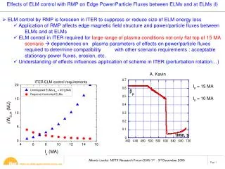
Understanding ELM size requires understanding transport processes • ELM size shows a strong dependence on collisionality • Cause for concern on ITER • Must identify the origin of the collisionality scaling • Likely nonlinear physics Loarte (PPCF 2003)
Behaviour of the pressure gradient Saturated gradient, non-linear phase! ASDEX Upgrade Burckhart, PPCF, 2010 Non-linear physics is important!
Nonlinear ballooning Theory • Progress can be made analytically for the early nonlinear evolution (Wilson, Cowley PRL 2004) • Predictions are • Initially sinusoidal mode narrows in direction across field lines, in flux surface • Mode tends to broaden radially, forming field-aligned filamentary structures • Even at linear marginal stability, as one enters nonlinear regime, mode suddenly erupts • Maximum displacement is on outboard side (identical to linear structure along field line), elongated along magnetic field lines • Filament could strike material surface on outboard side while remaining connected to pedestal on inboard • Potential damage to plasma-facing components, especially on ITER SOL PEDESTAL CORE
Non-linear simulations of ELMs Non-linear MHD code JOREK solves the time evolution of the reduced MHD equations in general toroidal geometry Density time Hyusmans PPCF (2009)
Non-linear simulations of ELMs Formation of density filaments expelled across the separatrix. Hyusmans PPCF (2009) Density filament, not the temperature 1 2 3
Nonlinear MHD modelling: Transport processes • Nonlinear MHD codes can probe the transport processes during the ELM • JOREK: electron heat transport dominated by parallel conductivity; density is convected into SOL; ion heat is a mixture • BOUT++ and JOREK observe stochastic magnetic field at the edge, which seems to play a role in the transport Xu, Dudson, et al, PRL 2010
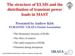
ELM Filament Observations.Fast cameras (eg MAST) The predicted structure of an ELM in theMAST tokamak plasma geometry, based on the nonlinear ballooning mode theory High-speed video image of the MAST plasma obtained at the start of an ELM
ELM Filament Observations • Fast cameras provide the most direct observation of filaments • They twist to align with magnetic field lines as they erupt • One can measure their ejection velocity: clear acceleration on MAST, but constant velocity on AUG • Filaments scale with machine size, and are oval: extent more in flux surface than radial A Kirk JNM 2009
ELM filament observation: Thomson scattering • TS measurements of filaments on MAST and JET provide a measure of the thermal energy stored in a filament: JET MAST M Beurskens, PPCF 2007 • Assuming Ti=Te, stored energy in filament~2.5% ELM energy loss • 10 filaments only account for ~25% of the loss • Another mechanism operates (filament syphoning energy from pedestal, or something else?) A Kirk, PRL 2006
ELM size reduction by pellet injection Type-I ELM frequency can be increased by injection of small deuterium pellets, provided that pellet freq. > 1.5 natural ELM freq. (results from AUG) Can the effects of plasma fuelling and ELM pacing be decoupled? P T Lang, et al., Plasma Phys. Control. Fusion 46 (2004) L31–L39 fPel > 1.5 f0ELM AUG
Non-linear MHD simulations of pellets injected in the H-mode pedestal Simulations of pellets injected in the H-mode pedestal show that pellet perturbation can drive the plasma unstable to ballooning modes. • A strong pressure develops in the high density plasmoid, in this case the maximum pressure is aprox. 5 times the pressure on axis. • There is a strong initial growth of the low-n modes followed by a growth phase of the higher-n modes ballooning like modes. • The coupled toroidal harmonics lead to one single helical perturbation centred on the field line of the original pellet position. JOREK G T A Huysmans, PPCF 51 (2009)
Experiments of Active Control of ELMs with a RMP on DIII-D Tokamak Internal coil (I-coil) T. E. Evans,et al., PRL, 92, 235003 (2004) T. E. Evans,et al., Nature physics, Vol. 2, p419, June 2006 T. E. Evans, et al., Phys. Plasmas 13, 056121 (2006).
Dominant mechanism of ELM suppression Reduction of edge pressure below instability threshold T. E. Evans,et al., Nature physics, Vol. 2, p419, June 2006 Density Electron temperature Ion temperature
Error field correct coils (EFCC) on JET IEFCC = 1 kAt; Bt= 1.84 T • Depending on the relative phasing of the currents in individual coils, either n=1 or n=2 fields can be generated • ICoil ≤ 3 kA x 16 turns (n = 1 and 2) • R ~ 6 m; Size ~ 6 m * 6 m • Br at wall ~ 0.25 mT/kAt Y.Liang et al., PPCF 2007
Active ELM control with n = 1 magnetic perturbation field on JET 14 16 18 20 22 24 Ip = 1.8 MA; Bt = 2.1 T; q95 ~ 4.0; dU ~ 0.45 JET#69557 Heat flux onto the outer divertor IEFCC (kA) Field off off On nel (1020m-2) Centre edge Da Times (s) Active ELM control (frequency/size) observed in a wide q95 window, but no ELM suppression Y Liang, et al, PRL, 98, 265004 (2007) Y Liang, et al, PPCF , 49, B581 (2007) Y Liang et al, JNM, 390–391, 733–739 (2009)
Edge ergodisation q=m/n q=(m+1)/n Chirikov parameter larger than 1 Equilibrium Magnetic Field at Plasma Edge • Splitting of strike point • Spin-up plasma rotation to co-current direction Edge Ergodisation with a magnetic perturbation
ELM suppression window on DIII-D • ELM suppression achieved in a narrow q95 window on DIII-D with an n=3 field induced by the I-coils. • q95 ELM suppression window can be enlarged slightly with a mixed n=1 and n=3 fileds. T.E. Evans, et al., NF 48 (2008) 024002
Threshold of ELM suppression T. E. Evans et al Nature Physics 2 (2006) 419 There is a threshold of ELM suppression in the amplitude of the n = 3 field.
Toroidal evolution of strike point s s • Field line tracing in vacuum approximation (superposition of equilibrium and perturbation field) • No screening of RMP by poloidal rotation • Ergodic field lines form lopes which generate multiple strike points on the divertor • Strike point splitting depends on toroidal position • Footprint represents N=2 symmetry of perturbation field D. Harting, JET science meeting 2010
Strike point splitting on DIII-D Splitting of the inner strike-point has been observed during ELM suppression with an n = 3 field on DIII-D. I. Joseph JNM, 2007 O. Schmitz, PPCF (2008)
Nonlinear simulations of ELMs Hyusmans PPCF (2009) Toroidal direction A poloidal and toroidal cut of the plasma temperature
Influence of magnetic perturbation on the Edge Electric field and rotation DIII-D 3kA I-coil current 0 I-coil current With an n = 3 field applied, edge Er more positive; spin-up plasma rotation in co-current direction, A large enhancement of the electron losses rather than ions by reason of the edge ergodisation. K. Burrell, PPCF 47, B37, 2005
Criterion for ELM suppression with RMPs M.J. Schaffer, et al., IEEE (2009); NF (2008) • Chrikov parameter number larger than 1 in the edge layer (sqrt(ψ) >0.925).
Effect of plasma shielding of the RMP M. Heyn, JET science meeting, 2010 • The resonant perturbation is shielded due to plasma rotation and the magnetic field topology in the plasma core is not affected by RMP's.
Influence of magnetic perturbation on X-point Enhancement of ergodisation; η(%) 100 50 0 -50 -100 0 1000 2000 3000 Connection length (m) JET 3-D Equilibrium calculation by HINT2 Code Vacuum • Flattening of j and p at the islands leads to an ergodisation at the island X-points • Strong enhancement of ergodisation at the X-point region due to plasma response may explain the density pump-out seen already at a small amplitude of the pertubation field C. Wiegmann, et al, EPS2009, P1.132
Observations of Multi-Resonance Effect in ELM Control with Perturbation Fields on the JET Y. Liang et al., PRL 105, 065001 (2010) A model in which the ELM width is determined by a localized relaxation to a profile which is stable to peeling modes can qualitatively predict this multi-resonance effect with a low n field. The dominant unstable peeling mode number and ELM frequency depends on the amplitude of the normalized edge currents as well as q95. • Multiple resonances in fELM vs q95 have been observed with n = 1 and 2 fields • The mechanism of edge ergodisation, can not explain the multi-resonance effect observed with the low n fields on JET. • Possible explanation in terms of ideal peeling mode model by Gimblett,PRL,2006.
ELM control coils on AUG W Suttrop, Fusion Engineering and Design 84 (2009) 290 In 2011: Two rows ×4 toroidally distributed coils (n = 2). Single DC supply (all coils in series / anti-series).
ELM mitigation on AUG Resonant and non-resonant variants work in the same way! … which is in contradiction to stochastic hypothesis… W Suttrop, PRL (2010)
ELM mitigation on AUG density is around the threshold density is above the threshold (mitigation)
Summary of ELM suppression/control with RMP • DIII-D n = 3, I-coils • ELM suppression in a narrow range of q95 • ELM mitigation in a wide range of q95 • JET n = 1, 2 EFCC • ELM mitigation • global effect in a wide range of q95 • multi-resonance effect in multiple narrow q95 windows • MAST n = 1, 2 EFCC; n=3 i=coils • ELM mitigation (q95 dependence) • AUG n = 2 B-coils • ELM mitigation in a relative wide range of q95 • Thresholds for RMP ELM mitigation
Summary of ELM suppression/control with RMP • Is the amplitude of the effective RMP important? Yes • Plasma Rotational screening effect • Field penetration Yes, but how deep the RMP field have to penetrate into a plasma for ELM suppression? • Is the target plasma itself important? Yes • Operation regime (ELM stability) Unknown • Plasma shaping (ELM stability) not very important • Collisionality (depending on the device; Unknown) • q95 Yes • Beta dependence? ( DIII-D Yes)
RMP ELM control Experiments DIII-D existing DIII-D planned JET EFCC & In-vessel coils (planned) ASDEX-U NSTX MAST TEXTOR + EAST …… providing input to modelling for ITER.
Combination of different techniques ASDEX Upgrade External coils + pellets Central density could be increased up to Recent result !! Lang Nucl. Fusion 52(2012) 023017