Download
1 / 1
10 likes | 150 Views
CISM Cone Model Approach to Interplanetary CME (ICME) Simulation D. Odstrcil 3,4 , X-P. Zhao 5 , Y. Liu 5 , T.J. Hoeksema 5 , C.N. Arge 6 , S. Ledvina 1 , P.Riley 2 , J. Linker 2 1 University of California, Berkeley, 2 SAIC, 3 University of Colorado, 4 NOAA-SEC, 5 Stanford, 6 AFRL.

E N D
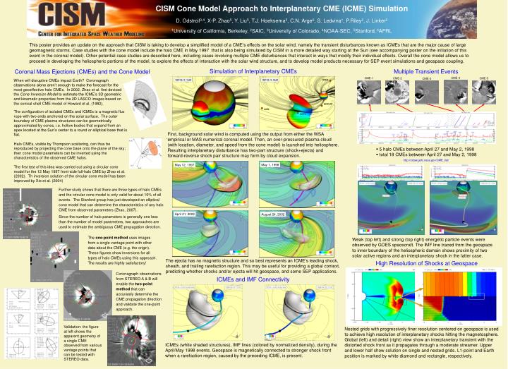
CISM Cone Model Approach to Interplanetary CME (ICME) Simulation D. Odstrcil3,4, X-P. Zhao5, Y. Liu5, T.J. Hoeksema5, C.N. Arge6, S. Ledvina1, P.Riley2, J. Linker2 1University of California, Berkeley, 2SAIC, 3University of Colorado, 4NOAA-SEC, 5Stanford, 6AFRL This poster provides an update on the approach that CISM is taking to develop a simplified model of a CME’s effects on the solar wind, namely the transient disturbances known as ICMEs that are the major cause of large geomagnetic storms. Case studies with the cone model include the halo CME in May 1997 that is also being simulated by CISM in a more detailed way starting at the Sun (see accompanying poster on the initiation of this event in the coronal model). Other potential case studies are described here, including cases involving multiple CME disturbances that interact in ways that modify their individual effects. Overall the cone model allows us to proceed in developing the heliospheric portions of the model, to explore the effects of interaction with the solar wind structure, and to develop model products necessary for SEP event simulations and geospace coupling. Simulation of Interplanetary CMEs Multiple Transient Events Coronal Mass Ejections (CMEs) and the Cone Model CME-4 CME-1 CME-2 CME-5 CME-3 When will disruptive CMEs impact Earth? Coronagraph observations alone aren’t enough to make the forecast for the most geoeffective halo CMEs. In 2002, Zhao et al. first devised the Cone Inversion Model to estimate the ICME’s 3D geometric and kinematic properties from the 2D LASCO images based on the conical shell CME model of Howard et al. (1982). CME-3 The configuration of isolated CMEs and ICMEs is a magnetic flux rope with two ends anchored on the solar surface. The outer boundary of CME plasma structures can be geometrically approximated by cones, i.e. hollow bodies that expand from an apex located at the Sun’s center to a round or elliptical base that is flat. Halo CMEs, visible by Thompson scattering, can thus be reproduced by projecting the cone base onto the plane of the sky; then cone model parameters can be inverted using the characteristics of the observed CME halos. The first test of this idea was carried out using a circular cone model for the 12 May 1997 front-side full-halo CME by Zhao et al. (2002). Th inversion solution of the circular cone model has been improved by Xie et al. (2004) First, background solar wind is computed using the output from either the WSA empirical or MAS numerical coronal model. Then, an over-pressured plasma cloud (with location, diameter, and speed from the cone model) is launched into heliosphere. Resulting interplanetary disturbance has two-part structure (shock+ejecta) and forward-reverse shock pair structure may form by cloud expansion. . • 5 halo CMEs between April 27 and May 2, 1998 • total 18 CMEs between April 27 and May 2, 1998 http://cdaw.gsfc.nasa.gov/CME_list/ May 1, 1998 May 12, 1997 CME-2 CME-3 CME-4 CME-5 CME-1 Further study shows that there are three types of halo CMEs and the circular cone model is only valid for about 10% of all events. The Stanford group has just developed an elliptical cone model that can determine the characteristics of any halo CME from observed parameters (Zhao, 2007). Since the number of halo parameters is generally one less than the number of model parameters, two approaches are used to estimate the ambiguous CME propagation direction. April 21, 2002 August 24, 2002 The one-point method uses images from a single vantage point with other data about the CME (e.g. the origin). These figures show inversions for all types of halo CMEs using this approach. The results are highly satisfactory! Weak (top left) and strong (top right) energetic particle events were observed by GOES spacecraft. The IMF line traced from the geospace to inner boundary of the heliospheric domain shows proximity of two solar active regions and an interplanetary shock in the latter case. High Resolution of Shocks at Geospace The ejecta has no magnetic structure and so best represents an ICME’s leading shock, sheath, and trailing rarefaction region. This may be useful for providing a global context, predicting whether shocks and/or ejecta will hit geospace, and some SEP applications. Coronagraph observations from STEREO A & B will enable the two-point method that can accurately determine the CME propagation direction and validate the one-point approach. ICMEs and IMF Connectivity Nested grids with progressively finer resolution centered on geospace is used to achieve high resolution of interplanetary shocks hitting the magnetosphere. Global (left) and detail (right) view show an interplanetary transient with the distorted shock front as it propagates through a moderate streamer. Upper and lower half show solution on single and nested grids. L1-point and Earth position is marked by white diamond and rectangle, respectively. Validation: the figure at left shows the apparent geometry of a single CME observed from various vantage points that can be tested with STEREO data. ICMEs (white shaded structures), IMF lines (colored by normalized density), during the April/May 1998 events. Geospace is magnetically connected to stronger shock front when a rarefaction region, caused by the preceding ICME, is present.