Download

1 / 25
250 likes | 448 Views
Proton Source Workshop Pre-accelerator Operations. Dan Bollinger. Talk Outline. Introduction Ion source fundamentals Ion source operations Haefely operations Summary. Introduction. There are two Cockcroft-Walton pre-accelerators H- and I-. The need for two is redundancy.

E N D
Proton Source Workshop Pre-accelerator Operations Dan Bollinger
Talk Outline • Introduction • Ion source fundamentals • Ion source operations • Haefely operations • Summary
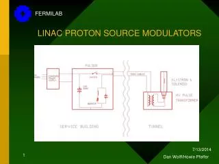
Introduction There are two Cockcroft-Walton pre-accelerators H- and I-. The need for two is redundancy. At the end of each accelerating column is a chopper that sets the accelerated beam pulse width. Since the beam coming out of the accelerating column has no bunch structure, there is a buncher prior to the entrance to tank one to provide bunched beam for acceleration in the drift tube linac (DTL).
Each Pre- acc consists of 2 main parts Slit aperture H- ion source Accelerating column The accelerating column typically runs at 745kV. Each accelerating gap (other than the 1st one) has to hold off at least 100kV.
Negative ion source (magnetron) The ion source resides in the dome at the upstream end of the column Source from column perspective Ref: C. Schmidt; Proton and H- sources at Fermilab Jan 31 2002 Ion source points down. The H- is extracted and bent 90deg to enter accelerating column
Negative ion source fundamentals Source operation relies on surface plasma effect Plasma produces energetic particles that strike the cathode surface H- ions are produced by desorption or reflection from a cesium coated cathode surface Ref: C. Schmidt; Proton and H- sources at Fermilab Jan 31 2002 Ref: C. Schmidt; Proton and H- sources at Fermilab Jan 31 2002 • Cesium on cathode lowers work function of molybdenum (Mo) cathode to enhance H- production: • Work function for Mo is 4.6eV • Work function for Mo + Cs is 1.8eV • Lowest work function when there is a 0.6 monolayer of Cs • Cs must be used in order to get 10’s of mA of H- Ref: Handbook of ion Sources; Bernard Wolf
Typical Source Operating Parameters The high arc current and low power efficiency contribute a large amount to the source aging and failure mechanisms. Typical source lifetime is ~ 3.5 months.
Ion source operations Typical source aging Cesium inlet hole in anode (new anode) • The high arc current causes erosion of the cathode. The cathode material ends up either depositing on the anode or flakes off. • The use of cesium and hydrogen causes cesium hydride buildup. Cesium hydride restricting hydrogen gas inlet to source Cesium inlet hole after source removed from operation Cathode material is deposited on anode plugging cesium inlet
Ion source operations Typical source aging Cathode erosion near anode cover plate extraction aperture Anode aperture erodes over time. This opening set the beam size coming out of the source. The emittance changes over time.
Ion source operations Typical source aging Hydrogen pressure in the source finally gets high enough that electrons are stripped off the H- and the amount of extracted H- beam current goes down. Need to decrease pressure to keep the source output up. Gas valve pulse width knobbed earlier tin time to allow more time for the gas to flow through the valve opening as cesium hydride builds up and restricts the aperture Hydrogen pressure needs to be increased as molybdenum from the cathode blocks the cesium inlet opening
Typical ion source failures Molybdenum from cathode blocks anode aperture, often cutting the beam current by 50% instantly. Molybdenum flake restricting the anode aperture Molybdenum flakes can also cause a short from anode to cathode. Shown here is the arc current jumping from 50A to 90A and the H- beam current going from ~55mA to 0.
More source issues 1 2 3 4 5 6 7 8 Latest problem is the hydrogen gas valve changes with the pit/dome temp. It clearly affects the amount of beam coming out of the source. After I- column repair we were not able to get sources to run in the column. From November 2009 to February 2010 it took 8 tries to get a source to finally survive in the new column. This type of problem causes a loss of redundancy.
Haefely Operations Voltage multiplier Metering resistor Drive shaft leg • Haefely controls are a mixture of 80’s and 60’s technology. There are vacuum tubes, relay logic, and stepper motor controls along with op amp circuits. • Technicians that originally built and maintained this system for over 40yrs retired in 2009. Motor for generator
Haefely Operations • The Haefely HV regulation electronics are 1980’s vintage op amp circuits. They regulate the HV typically to within ± 2kV • The water resistor needs to be flushed on a regular basis to maintain proper voltage drop across the accelerating column Typical water resistor contamination HV regulation over a 2 day period Prior to 2010 shutdown the H- column water resistor needed flushed 1/month. This is about 1hr of downtime 3kV envelope
Haefely maintenance Part of the Haefely scheduled maintenance includes rebuilding the generator and drive shaft couplings every 3 years. This takes about 2 weeks. The generator brushes need to be replaced every 2 to 3 weeks. This is about 45min of downtime. I- drive shaft couplings had to be rebuilt twice. This process took about 3 weeks.
Recent Haefely problems HV regulation became unstable after event $21 were placed in the timeline. The line voltage varied by ~ 1eV causing the regulation card to over react. Took over 2 weeks to re-adjust the regulation card for stable running. The 2009 failure of the I- accelerating column left us without any redundancy for over 3 months. The anode power supplies have had several recent fan failures which causes damage to the supply.
Misc. routine maintenance Ion pumps for the accelerating column need rebuilding every 1 to 2 years • Quad magnets in the accelerating column need to be flushed due to over heating problems. • Haefely pit AC unit needs a fair amount of maintenance due to age. • Pit humidifier needs repair ~1/season
Summary • The magnetron ion source lifetime is mostly due to the low power efficiency causing the cesium inlet to clog with cathode material, along with anode aperture restrictions and cathode/anode shorts. • The fact that cesium and hydrogen are need for the source causes the hydrogen inlet to become restricted with cesium hydride. • There is still much that is unknown about negative ion source operation. • Failures of the Haefely systems put us at a significant risk due to the loss of redundancy for extended periods of time. • The Haefely requires extensive maintenance for continuous operation. • The retirement of the skilled technicians that originally built and maintained the Cockcroft-Walton accelerators for over 40yrs has left us vulnerable to significant downtime in the future if there is a major Haefely failure.
I- column repair 1st time new column has been built in over 25yrs !! Column pulled off of wall New column built on site Ceramic severely damaged New column has been installed and conditioned to 760kV
Proposed ion source configuration Current H- extraction/acceleration scheme. Dome sits at -750kV and H- is extracted out of the source at 12 to 18kV. We need to run with ~50A of arc current to get 50mA of H- beam current. The efficiency is on the order of 9mA/kW Proposed H- extraction/acceleration scheme. The acceleration voltage is the extraction voltage. This is very efficient at pulling H- out of the source. So, we should only need to run with ~ 15A of arc current. This leads to a power efficiency of 67mA/kW. The lower power being dumped into the source should increase the longevity of the source.
Work functions Tungsten could be used for cathode material
H- source ion pump problems Ion pump out gassing due to end of life Out gassing affects on source operation Increasing frequency and magnitude of ion pump out gassing near end of pump life • Increases in gas pressure perturbs feedback loops • Instabilities in source take fair amount of time to recover from
I- column failure Prior to shut down the I- column would not hold off above 500kV with out arcing over Hipot of column showed 1 accelerating gap was the problem