Download
1 / 32
430 likes | 855 Views
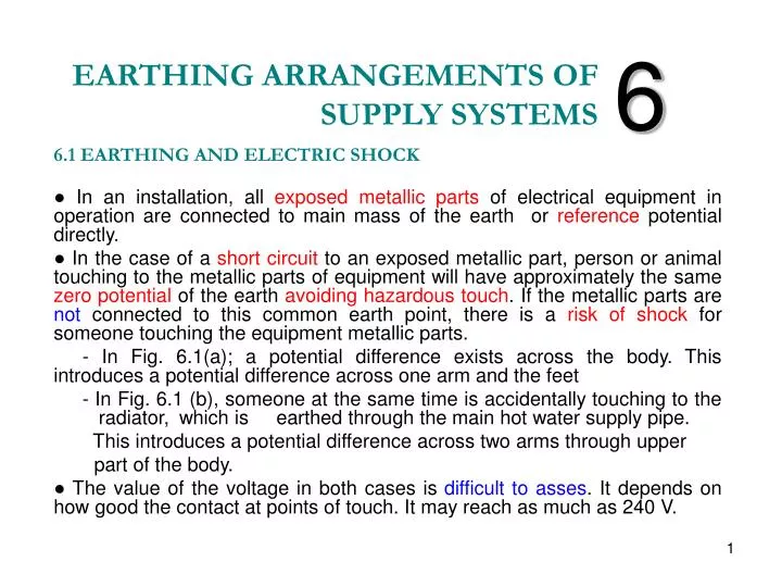
EARTHING ARRANGEMENTS OF SUPPLY SYSTEMS. 6. 6.1 EARTHING AND ELECTRIC SHOCK ● In an installation, all exposed metallic parts of electrical equipment in operation are connected to main mass of the earth or reference potential directly.

E N D
EARTHING ARRANGEMENTS OF SUPPLY SYSTEMS 6 6.1 EARTHING AND ELECTRIC SHOCK ● In an installation, all exposed metallic parts of electrical equipment in operation are connected to main mass of the earth or referencepotential directly. ● In the case of a short circuit to an exposed metallic part, person or animal touching to the metallic parts of equipment will have approximately the same zero potential of the earth avoiding hazardous touch. If the metallic parts are not connected to this common earth point, there is a risk of shock for someone touching the equipment metallic parts. - In Fig. 6.1(a); a potential difference exists across the body. This introduces a potential difference across one arm and the feet - In Fig. 6.1 (b), someone at the same time is accidentally touching to the radiator, which is earthed through the main hot water supply pipe. This introduces a potential difference across two arms through upper part of the body. ● The value of the voltage in both cases is difficult to asses. It depends on how good the contact at points of touch. It may reach as much as 240 V.
Figure 4.1 The electric shock hazards in installation without earthing.
● To ensure safety in the area of a consumer electrical installation, and to avoid any possible shock and fire risk in the case of a fault, the metallic parts of equipment must be kept at any potential close to that of the earth potential i.e. at zero volt. ● In both cases of Fig. 4.1, the safe operation is achieved by connecting the metallic parts of the equipment to the earth potential.This connection brings all the metallic parts to the earth potential. This case is illustrated in Fig. 4.2. In Fig. 4.2 (a), exposed metallic parts of the equipment and in Fig. 4(b), extraneous metallic parts in the vicinity of an earthed equipment are connected to the main earthing terminal of the installation, so that all metallic parts in the installation have the same potential or equipotential. ● Joining together (bonding) all metallic parts and connecting to the earth is known as equipotential bonding.
Figure 4.2 Earthing and bonding conductors in an installation.
Definitions of earthing terms In an installation earthingexposed metallic parts of equipment and the other extraneousmetallic parts in the installation is achieved by connecting them to the main earthing terminal (MET) at the consumer's DB via a protective earth conductor (PE). The MET is connected to the earth electrode via main earthing conductor. Description of some of the earthing terms are given in Fig. 4.2(b). Protective earthing conductor (PE) The conductor which connects the MET to the earth electrode, or to the other means of earthing. Exposed conductive parts (EXPC)They are accessible parts of equipment which are not live, but could be live in the case of a fault. Extraneous conductive part (EXTC)It is a conductive part which is not part of the electrical installation, but can introduce a potential generally that of the earth. Equipotential bonding conductor (EQP)It is the conductor which brings the exposed conductive parts of the equipment and extraneous conductive parts to the same potential. Consumer's main earthing terminal. It is the terminal or a bar provided for the consumer 's DB to connect PE of all final circuits, the equipotential bonding conductor, and to the conductors for functional earthing. Functional earthing.It is earthing of one or more points in a system or items of equipment, which do not perform electrical safety function, but is necessary for proper function of the equipment.
4.2 EARTH ELECTRODE SYSTEM (IEE Reg. 542-02-01) The earth itself is not a good conductor unless it is wet. Its resistance restricts the flow of fault current. A good conducting path for the flow of fault current is achieved by providing a good connection to the earth. There are several connection methods to the earth using: - conductor earthing electrodes - burried earthing electrodes (i) Conductor earthing electrodes may have the form of strip or round or stranded material, and can be installed in radial, ring, or mesh (Fig. 4.3(b)-(f)). (ii) Rod earthing electrodes are of rod type and burried in vertical position at a considerable depth. They can be installed as individual in radial, ring, or mesh configurations for establishing an active earth conductor connection (Fig. 4.3(a)). Figure 4.3 Earthing electrodes: (a) Earthing rod (b) Burried wire. (c) Burried strip. (d) Thin disk plate near the soil surface. (e) Ring. (f) Mesh.
Earth electrode Resistance The resistance of any electrode system, illustrated in Fig. 4.3, varies with soil resistivity, humidity and temperature as well as with the type of earthing electrode system, and can be estimated simply using the following formulas. • Rod electrode • Burried wire (c ) Burried strip (d) Thin disk (e) Ring (in infinite medium) (f) The expression for earthing resistance of a mesh is complex, but may be approximated as a semi-sphere having a diameter of b.
Materials The conductor materials to be used as earthing electrode should resist corrosive conditions or to be protected from corrosive conditions The materials which fulfil these requirements are: - copper, - aluminium - copper-clad aluminium The conductors to be used for an earthing system should be continuous with no joints, and may preferable be driven into soil as bare solid rod, connections between driven rods as stranded. Size of Earthing Electrode(IEE On-Site Guide) For TN-S and TN-C-S supplies the minimum size of buried earthing conductor 16 mm2 copper or greater. For TT supplies both conductor sizes also applies. 25 mm2 copper or 50 mm2 steel if not protected against mechanical damage or corrosion. See A10 of IEE Guide for the sizes PE and bonding conductors.
Earth soil resistivity The earth resistance of a grounding electrode mostly depends on the soil resistivity and type of grounding electrode. The soil resistivity varies with (i) type of soil and its granular structure, (ii) the moisture content and (iii) the amount of dissolved salts in the soil. (Table 4.1). Because of the importance of the moisture, it is preferable to bury the earth electrode to a depth where the condition for dampness achieves a stable value. The resistivity of soil may be measured using the earth electrode using the expression given for a rod Table4.1 Reference values for the soil resistivity for various soil types.
4.3 SUPPLY SYSTEM ARRANGEMENTS There are several types of arrangements for the supply systems that the consumer’s MET is connected to the supply earth point. These are classified in IEE Reg. 312-03-01 as applied in practice as: TN-S system, TN-C-S system, TT system, TN-C system, and IT system. This grouping is based on earthing of the supply systems and defined by the letters. - The first letterT (Terra =Earth): It indicates that at least one point of the supply is connected directly to the earth or isolated from the earth. - The first letterI (Isolated): It indicates that the earth point of the supply is isolated from the earth in an industrial plant. - The second letterN(Neutral): It shows whether exposed conductive parts in the installation are connected directly to the earth point at the source supply or not. - The third and final letters (C, C-S, S): These indicate the arrangement of the equipment protective conductor and neutral conductor serving TN system.
The letter C shows both protective and neutral conductors are combined together. This could be formed in a single or multicored cable and known as PEN conductor. The letter S shows both protective and neutral conductors are separate from each other. All of the following power supply systems except IT system are used for public supplies. 1. TN-S Supply System This is one of the popular types of supply system in that the electricity authority provides the supply to the building by underground cables. Fig. 4.4 illustrates the circuit wiring for TN-S supply arrangement to consumer's DB. In this system of connection:
Figure 4.4 Single-phaseTN-S supply system. Notice the function of cable metal sheath as PE conductor in (a) single-phase and (b) three-phase distribution systems.
- Neutral and PE conductors run separate throughout the system. - PE conductor is the metal sheath or armour of the underground cable or a separate conductor and is connected to the consumer's main earthing terminal (MET) in DB. - All exposed conductive parts of the installation are connected to MET in consumer DB. Figure 4.5 TN-S supply system serving single and three-phase equipment.
Figure 4.6 Single-phaseTN-S supply system. (a) Connection of PE conductor to cable armour. (b) Wiring diagram.
2. TN-C-S Supply System (PME) This type of underground supply arrangement has been recently started to supply installations because of its proven safety. This arrangement is also known as protective multiple earthing (PME). - The functions of both protective and neutral conductors are combined in the supply cable (PEN conductor) (Fig. 4.7(b)). - The consumer's MET is formed by connecting the neutral of supply cable in the consumer's installation or DB. - All exposed metallic parts such as installation gas, water pipes etc. are then connected to MET and the neutral terminal. These terminals are joined together. - Thus, phase-to-earth faults are effectively converted into phase-to-neutral faults. - The combined and neutral conductor (PEN) should be earthed many times throughout the supply authority's distribution system.
3. TT Supply System This type supply arrangement should be applied when the installation is fed from overhead lines. The supply authorities do not provide protective earthing to the premise. In this case a residual current device RCCB must be included in in the installation (Fig. 4.8) +- All the exposed conductive parts of the installation are connected to the earth electrode through MET of the installation and is independent of the supply earth. Figure 4.8 TT-supply system.
4. TN-C Supply System In this system of connection the neutral and protective functions of the supply are combined in a single conductor (PEN) throughout the system (Fig. 4.9). - This supply system is applied to privately owned generating plants or transformers where there is no connection between the TN-C system and the publics supply. All exposed conductive parts of the installation are connected to the PEN conductor. As both protective and neutral conductors are combined, RCCB cannot be used with this type of installation. Figure 6.9 TN-C supply system
5. IT Supply System The supply (transformer) is isolated from the earth with a highly ohmic earthing resistor ( Fig. 6.10). - In this case any fault involving the earth there is no shock or fire risk. - If a fault occurs, type of earth may be detected and identified using monitoring equipment, and an audible or similar warning may be produced. - This type of supply arrangement is used in mines, quarries and chemical factories where interruption of the operation or processes may create hazardous situations. - This system of connection must not be used for public supplies and its usage is limited to private generating plants. Figure 6.10 ITsupply arrangement.
6.5 EARTHING CONNECTION IN MAIN SWITCHBOARD AND DISTRIBUTION BOARDS In large scale domestic or commercial installations supplied by the local private transformer, having a set of SDB or DBs, directly supplied from the main substation switchboard or from the main distribution board, the earthing connection usually follows TN-S supply arrangement (Fig. 6.11) - The main earthing in the MDB or substation switchboard is usually a busbar, called main earthing busbar (ME busbar). - In installations using two SDBs, as in workshops or factory halls, PE conductors of both SDBs are separately connected to ME busbar in main DB and finally to ME busbar of the substation switchboard.
Figure 6.11 TN-S supply arrangement in a TPN distribution system
6.6 ELECTRICAL BONDING The purpose of bonding is to keep all the exposed metalwork in the interior of a premise at the same earth potential as the metalwork of the electrical installation, so that no potential difference exists between them to cause an electric shock. This connection or bonding of all exposed metalwork in an installation is known as equipotential bonding. Depending upon types of exposed metalwork involved in bonding the Regulations imposes different restrictions. 6.6.1 MAIN EQUIPOTENTIAL BONDING To avoid possible potential difference between exposed metallic parts of earthed electrical equipment and metalwork of other services must be effectively connected to the main earthing terminal (MET) of the installation. The other electrical and non-electrical services described in the Regulation are: - main water and gas pipes, - other service pipes and ducting, - risers, ducts of central heating and air conditioning systems, - extraneous metal parts of the building structure - lightning protective conductors.
Figure 6.12 An example of main equipotential bonding arrangements of water and gas supply pipes in a TN-S connected supply arrangement.
Main equipotential bonding (MEB) should be made to water and gas services at their entry point to the building as shown in Fig. 6.12. - The connecting conductor, known as MEB conductor, should be insulated - The minimum permitted size ,6 mm2≤ (AC)min <25 mm2. - In domestic and small commercial premises the bonding clamp must be fitted on the consumer side of meters (gas and water) before any branch pipework, but within 60 cm of the meter. A permanent label also must be fixed at or near the point of connection of MEB conductors for safety warning. 6.6.2 SUPPLEMENTARY EQUIPOTENTIAL BONDING This bonding requires all exposed extraneous conductive parts within closevicinity of a non-electrical metalworks (water pipes etc) already being connected with MEB conductor to maintain the equipotential zone created by the MEB (Fig. 6.13).
Figure 6.13 An example of supplementary equipotential bonding arrangement in a bathroom area.
Supplementary bonding conductors to have a minimum cross-sectional area of AC=2.5 mm2 when mechanically protected (within conduit or mini-trunk ) or - if placed in an inaccessible position, and 4 mm2 if unprotected. 6.7 EARTH FAULT IMPEDANCE In an earthed and bonded installation in order to avoid shock and fire risks under fault conditions, it is required to ensure operation of protective devices at disconnecting times less than the permissible values (0.4 s or 5 s depending on circumstances). ■ This depends on the magnitude of the fault current, which is determined by the earth loop impedance (EFLI) in a faulty circuit. ■The value of this impedance in relation to the impedance defined for the protective device under short circuit conditions establishes disconnecting times for protection against; - shock for indirect contact - temperature rise in conductors The fault current is limited by the EFLI, Zs. In the case of a short circuit EFLI of the path in a TN-S supply arrangement involves;
Z1 - Impedance of the circuit protective conductor Z2 - Impedance of phase conductor of the final circuit from fault point to the consumer DB. Z3 - Impedance of protective earthing conductor Z4 - Impedance from the consumer DB to the source Z0 - Impedance of the source The total impedance of the short circuit path is Zs= Z0 + Z1+Z2 +2Z3 +Z4 Figure 6.14 Definition of earth-loop fault impedance path.
ZE= Z0+Z3+Z4 or ZS= ZE+ Z1+Z2 ZEmay be measured using a phase-to-earth loop impedance tester. However, at the design stage of an installation, if there is no other information about the supply transformer and the size of the supply cables, the following maximum values given by the supply authority may be used for different type of supply arrangements: TT : 21 , TN-S: 0.80 , TN-C-S: 0.35 EXAMPLE 6.1 A BS 3871 type 1 20-A MCB is used to protect a radial socket-outlet circuit in a kitchen environment. The cable length is 30 m and it incorporates 2.5-mm2 PVC cable and a 1.5-mm2 PE conductor. If the EFLI of the supply measured at DB is 0.45 ohm, determine the total EFLI of the circuit. Assume that the ambient temperature is 30 OC.
Solution. ZS = ZE + (Zline + ZPE ) The value measured at DB position, ZE= 0.4 Ohm The resistance of the line conductor at 30 OC or at the corresponding table temperature of 115 OC can be found using Table 6.1 as Zline = Rline=(10.226 x 30 m) x10-3 = 0.307 and of PE conductor at 30 OC or at the corresponding table temperature of 95 OC ZPE = RPE=(15.73 x 30 m) x10-3 = 0.472 The total EFLI is, therefore, ZS= 0.400 + (0.307+ 0.472) = 1.179 The value of Zs should be as low as possible in order to achieve effective protection against direct contact, when a fault occurs between the phase conductor and the protective conductor or an exposed metallic parts of the equipment,. to disconnect the supply within a specified time. That is, in order the PD to operate sufficiently rapidly, EFLI limit given for a PD, ZPD, should be less than or equal to EFLI of the final circuit, Zs, i.e., ZPD Zs IEE Tables 41B to 41D given for EFLI values under Regulations (413-02-09) to (413-02-13) are specified for the disconnecting time limits for PDs. The specified time limits for a PD is related to the type of final circuit and may be classified as follows:
A - The disconnecting time should not exceed 5 s for: (i) A final circuit supplying socket outlet or portable equipment (including hand-held Class I equipment) and (ii) A final circuit supplying only stationary equipment B - The disconnecting time is 0.4 s (Table 41A) for: A final circuit supplying socket outlets and to other final circuits, which supply portable equipment, intended for manual movement use or hand-held Class I equipment (Bathroom or kitchen condition) EXAMPLE 6.2 In Example 6.1 determine whether it is safe to operate the MCB (BS3871 type 1) for a kitchen (within 0.4 s) in this circuit or not. Solution. The maximum permitted value given for the MCB (Table 41B2) is 3 . Since Zs is less than this value, the PD will operate within the specified time limit of 0.4 s (kitchen condition). This means the sizes of conductors are sufficient for shock safe operation under short circuit conditions.