Download
1 / 30
540 likes | 1.49k Views
Earthing & Grounding. PRESENTATION BY: Iyer Yagneshwar(13BEEEG066) (130410109025) Shah Kunal(13BEEEG084)(130410109099) Joshi Jaivik(13BEEEV135)(130410109033) Chauhan Jill(13BEEEG091)(130410109013) Guided by-: Shital M Pujara. Concept of Earthing Systems.

E N D
Earthing & Grounding PRESENTATION BY: Iyer Yagneshwar(13BEEEG066) (130410109025) Shah Kunal(13BEEEG084)(130410109099) Joshi Jaivik(13BEEEV135)(130410109033) Chauhan Jill(13BEEEG091)(130410109013) Guided by-: Shital M Pujara
Concept of Earthing Systems All the people living or working in residential, commercial and industrial installations, particularly the operators and personnel who are in close operation and contact with electrical systems and machineries, should essentially be protected against possible electrification. To achieve this protection, earthing system of an installation is defined, designed and installed according to the standard requirements..
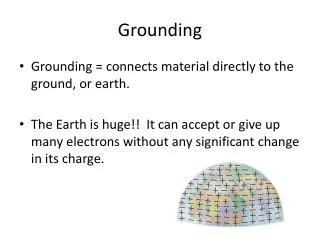
What Is Earthing The process of connecting metallic bodies of all the electrical apparatus and equipment to huge mass of earth by a wire having negligible resistance is called Earthing.
What Is Earthing The term earthing means connecting the neutral point of supply system or the non current carrying parts of the electrical apparatus to the general mass of earth in such a manner that all times an immediate discharge of electrical energy takes place without danger.
Objectives of the earthing • Provide an alternative path for the fault current to flow so that it will not endanger the user • Maintain the voltage at any part of an electrical system at a known value so as to prevent over current or excessive voltage on the appliances or equipment.
Qualities Of Good Earthing • Must be of low electrical resistance • Must be of good corrosion resistance • Must be able to dissipate high fault current repeatedly
Purpose of Earthing • To save human life from danger of electrical shock or death by blowing a fuse i.e. To provide an alternative path for the fault current to flow so that it will not endanger the user • To protect buildings, machinery & appliances under fault conditions ie. To ensure that all exposed conductive parts do not reach a dangerous potential. • To provide safe path to dissipate lightning and short circuit currents. • To provide stable platform for operation of sensitive electronic equipments i.e. To maintain the voltage at any part of an electrical system at a known value so as to prevent over current or excessive voltage on the appliances or equipment .
Electric shock • An electric shock (electrocution)occurs when two portion of a person’s body come in contact with electrical conductors of a circuit which is at different potentials, thus producing a potential difference across the body. • The human body does have resistance and when the body is connected between two conductors at different potential a circuit is formed through the body and current will flow • When the human body comes in contact with only one conductor, a circuit is not formed and nothing happens. When the human body comes in contact with circuit conductors, no matter what the voltage is there is potential for harm.
Electric shock • The higher the potential difference the more the damage. The effect of an electric shock is a function of what parts of body come in contact with each conductor, the resistance of each contact point the surface resistance of the body at the contact as well as other factor. • When the electrical contact is such that the circuit path through the body is across the heart, you have the greatest potential for death.
Equipment Earthing • In case of insulation failure, the primary object of connecting all the above points and apparatus to earth is to release the charge accumulated on them immediately to earth so that the person coming in contact may not experience electric shock.
Equipment Earthing(Cont.) The other object is that a heavy current when flows through the circuit that operates the protective devices that is fuse or CB, which open the circuit
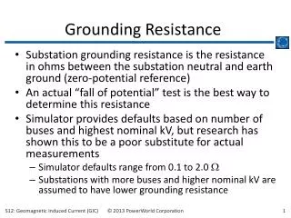
Max. Value of Earth Resistance to be achieved * The Earth Resistance depends upon the moisture content in the soil.
Methods of Earthing • Conventional Earthing • Maintenance Free Earthing
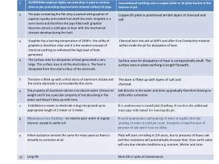
Conventional Earthing • The Conventional system of Earthing calls for digging of a large pit into which a GI pipe or a copper plate is positioned in the middle layers of charcoal and salt. • It requires maintenance and pouring of water at regular interval.
CONVENTIONAL EARTHING FIGURE:.
Maintenance Free Earthing • It is a new type of earthing system which is Readymade, standardized and scientifically developed. Its Benefits are • MAINTENANCE FREE: No need to pour water at regular interval- except in sandy soil. • CONSISTENCY: Maintain stable and consistent earth resistance around the year. • MORE SURFACE AREA: The conductive compound creates a conductive zone, which provides the increased surface area for peak current dissipation. And also get stable reference point.
Maintenance Free Earthing(Contd.) • LOW EARTH RESISTANCE: Highly conductive. Carries high peak current repeatedly. • NO CORROSION: • LONG LIFE. • EASY INSTALLATION.
Methods of Conventional Earthing • Plate Earthing • Pipe Earthing • Rod Earthing • Strip Earthing • Earthing through Water Mains
Earthing Electrode • The resistance of a ground • electrode has 3 basic • components: • A) The resistance of the ground • electrode itself and the connections • to the electrode. • B) The contact resistance of the • surrounding earth to the electrode. • C) The resistance of the surrounding • body of earth around the ground • Electrode. It consist of three basic components: • Earth Wire • Connector • Electrode
Plate Earthing • In this type of earthing plate either of copper or of G.I. is buried into the ground at a depth of not less than 3 meter from the ground level. • The earth plate is embedded in alternative layer of coke and salts for a minimum thickness of about 15cm. • The earth wire(copper wire for copper plate earthing and G.I. wire for G.I. plate earthing) is securely bolted to an earth plate with the help of bolt nut and washer made of copper, in case of copper plate earthing and of G.I. in case of G.I. plate earthing.
Pipe earthing • Pipe earthing is best form of earthing and it is cheap also in this system of earthing a GI pipe of 38 mm dia and 2meters length is embedded vertically in ground to work as earth electrod but the depth depend upon the soil conditions, there is no hard and fast rule for this. • But the wire is embedded upto the wet soil. • The earth wire are fastened to the top section of the pipe with nut and bolts. • The pit area arround the GI pipe filled with salt and coal mixture for improving the soil conditions and efficiency of the earthing system. • It can take heavy leakage current for the same electrode size in comparison to plate earthing. • The earth wire connection with GI pipes being above the ground level can be checked for carrying out continuity test as and when desired, while in plate earthing it is difficult. • In summmer season to have an effective earthing three or four bucket of water is put through the funnel for better continuity of earthing.
ROD EARTHING • In this system of earthing 12.5mm diameter solid rods of copper 16mm diameter solid rod of GI or steel or hollow section of 25mm GI pipe of length not less than 3 meters are driven vertically into the earth • In order to increase the embeded length of electrod under the ground, which is some time necessary to reduce the earth resistance to desired value more than one rod section are hammered one above the other. • This system of earthing is suitable for area which are sandy in character . • This system of earthing is very cheap
STRIP OR WIRE EARTHING • In this system of earthing strip electrod of cross section not less than 25mm into 1.6mm of copper or 25mm * 4mm of GI or steel are burried in horizontal trenches of minimum depth of 0.5m • If round conductor are used their cross sectional area shall not be smaller than three if copper is used and 6mm2 if GI or steel is used. • The length of burried conductor shall be sufficient to give the required earth resistance (about 0.5Ωto 1.5Ω) • It shall however be not less than 15 m • The electrod shall be as widely distributed as possible in a single straight or circular trenches radiating from a point • This type of earthing is used in rockey soil earth bed because at such places excavation work for plate earthing is difficult
Standard Pipe & Plate Type Earthing Design for the 11 Kv. System Equipments, Distribution Transformer Centers, L.T. Distribution System Equipments • Design Details : • Earthing Pit : Size 1000 X 1000 X 1800 mm Depth.M.S. / C.I. Plate : 500 X 500 X 8 mm Thick. • Electrode Assembly : 40 mm Ø GI / CI Perforated pipe duly fitted or welded with base plate and 50 X 6 mm flat termination taken on top for equipment earthing as shown in drawing.
Standard Pipe & Plate Type Earthing Design for the 11 Kv. System Equipments, Distribution Transformer Centers, L.T. Distribution System Equipments • Mixture - I : Homogeneous mixture of black soft soil 0.3 CMT. approx. • Mixture - II : Homogeneous mixture of common salt 25 Kgs. + wood charcoal pieces 25 Kgs. + Black soft soil 1 CMT. Approx. • Crushed Rock pieces Gravel Size 50 X 35 mm 0.1 CMT. Approx. • Arrangement for earthing lead terminations from equipment body, and connection for main earthing Grid.
Typical arrangement for Pipe electrode earthing pit (Bore Type) • Design Details : • 75 mm thick RCC Cover. • 300 mm Ø 6000 mm deep (Approx. 20 ft.) bore in the earth. • 65 mm Ø 6000 mm long (Approx 20 ft.) G.I. pipe electrode. Forged at the top up to 75 mm length and 12 mm hole provided for taking earthing connection. • A homogeneous mixture of 50 kgs. wooden coal pieces + 50 kgs. common salt • Water pouring purpose at the time of routine maintenance
Applications • Telecommunication • Transmission • Substations & Power Generations • Transformer Neutral earthing • Lightning Arrestor Earthing • Equipment Body Earthing • Water Treatment Plants • Heavy Industries • College, Hospitals, Banks • Residential Building