Download

1 / 24
240 likes | 375 Views
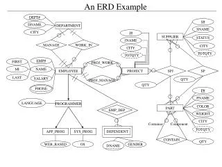
AN EXAMPLE. motor. valve. V R. V L. tank2. tank1. turbine. generator. V R. K. V M. +. K. V M. V R. -. V L. V L. Comparator. v M =K(v R -v L ). M. v M. T M. Motor (armature controlled). Motor data:. Armature winding resistance: R a. Armature winding inductance: L a.

E N D
motor valve VR VL tank2 tank1 turbine generator 1.7 An example
VR K VM + K VM VR - VL VL Comparator vM=K(vR-vL) 1.7 An example
M vM TM Motor(armature controlled) Motor data: Armature winding resistance: Ra Armature winding inductance: La Motor constant: KM Back e.m.f. constant: Kb Rotor inertia: JM Shaft friction: BM 1.7 An example
Ra La ia + eb - T Jm Bm Armature controlled D.C. motor - revisited if=cnt. 1.7 An example
ia ea T + Km - eb Kb T Model: A block diagram 1.7 An example
For the problem at hand eb T vM TM M BUT Mechanical load on the shaft should be the total load Including that due to the valve also 1.7 An example
ia + Km - eb Kb Block diagram for the motor M TM VM • Where BM* & JM* show the total including the load 1.7 An example
M TM Valve Data q0=KvM Shaft friction: Bv q0 Shaft inertia negligible 1.7 An example
Kv M M q0 Valve model q0=KvM sM=M and BM*=BM+Bv , JM*=JM 1.7 An example
q0 A1 A2 h1 h2 R1 R2 q1 q2 p1 p2 p3 Double tank:Definitions p1=h1 p2=h2 1.7 An example
q0 h1 q0 h1 + - q1 q1 p1 Analysis Rate of change of heightXcross sectional area =added volume per unit time 1.7 An example
p1 p2 R1 q1 h1 q1 + - h2 1.7 An example
h2 q1 h2 + q1 q2 - p2 q2 1.7 An example
p2 p3 R2 q2 h2 q2 + - p3 1.7 An example
q0 h1 + q1 + h2 - - h2 + q1 - q2 Block diagram for the double tank system 1.7 An example
p3 q2 TG G 0 Turbine Turbine inertia & friction negligible A lossless (transformer-like) element 1.7 An example
iF TG G Generator Rotor inertia: JG vL Bearing friction: BG Field controlled type Field inductance: LF Field resistance: RF 1.7 An example
Rf Lf if + ef T Jm Bm Field controlled D.C. motor Fix armature current! ia=Cnt. Tm=Kmif 1.7 An example
if ef T Km Block diagram model 1.7 An example
Lf Rf + vL IL ia=Cnt. if Jm JG Jm Bm Bm BG G TG 1.7 An example
TG G N KG BG+sJG h2 iF vL N q2 iF=KGTG 1.7 An example
M q0 M h1 q1 VL VM - + ωG if ia TG + + + + VR K Kv N BG+sJG KG RF+sLF - - - h2 - q2 VL N comparator motor valve double tank turbine-generator 1.7 An example
End of Chapter Restart section Next chapter Restart chapter i The End General index End show 1.7 An example