Download
1 / 16
190 likes | 397 Views
MANGANITE SENSORS ARRAY FOR MEASUREMENTS OF MAGNETIC FIELD DISTRIBUTION. Oliver Liebfried Gelsenkirchen University of Applied Science, Germany Semiconductor Physics Institute (SPI), Lithuania. Structure. Manganite Sensor Array Experimental arrangement Calculation Results Conclusion.

E N D
MANGANITE SENSORS ARRAY FOR MEASUREMENTS OF MAGNETIC FIELD DISTRIBUTION Oliver Liebfried Gelsenkirchen University of Applied Science, Germany Semiconductor Physics Institute (SPI), Lithuania
Structure • Manganite Sensor Array • Experimental arrangement • Calculation • Results • Conclusion Oliver Liebfried MANGANITE SENSOR ARRAY 21th Sep. 2006
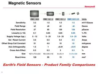
Manganite Sensor Source: Vilnius High Magnetic Field Centre • Size of 1x0.5mm • Made of La0.83Sr0.17MnO3 thin polycrystalline film • Sensitive to absolute value of magn.field (B-Scalar-Sensor) • Insensitive to changes of the direction of the B-vector • Tested for B < 50T Oliver Liebfried MANGANITE SENSOR ARRAY 21th Sep. 2006
Manganite Sensor Array • 4 B-Scalar-Sensors in a flexible tube • in distances of 5mm • fixed by customary glue • coated by wire screen Oliver Liebfried MANGANITE SENSOR ARRAY 21th Sep. 2006
Experimental arrangement Capacity: 2240μF Testing Voltage: 1000V Oliver Liebfried MANGANITE SENSOR ARRAY 21th Sep. 2006
Experimental arrangement Casing Coil z Carrier tube Projectile Sensor array Stopper Oliver Liebfried MANGANITE SENSOR ARRAY 21th Sep. 2006
M1112 L22 L11 L12 L21 u11 u22 u12 u21 M1121 M1221 R22 R12 R11 R21 M1221 M1122 M2122 Theory - Magnetically coupled circuits - Oliver Liebfried MANGANITE SENSOR ARRAY 21th Sep. 2006
Calculation - Basic equation system - Voltage equations: Equation of movement: System of ~50 differential equations Oliver Liebfried MANGANITE SENSOR ARRAY 21th Sep. 2006
Theory - Magnetic field - Magnetic field generated by each ring was calculated applying the following formula: r – radial position zn – axial distance to nth ring sn – radius of nth ring K,E – elliptic integrals of 1st & 2nd kind with Oliver Liebfried MANGANITE SENSOR ARRAY 21th Sep. 2006
Results - Fixed projectile arrangement - calculated measured Oliver Liebfried MANGANITE SENSOR ARRAY 21th Sep. 2006
Results 50 μs 250 μs 500 μs 700 μs Oliver Liebfried MANGANITE SENSOR ARRAY 21th Sep. 2006
Calculation - Results - Oliver Liebfried MANGANITE SENSOR ARRAY 21th Sep. 2006
Calculation - Results - Oliver Liebfried MANGANITE SENSOR ARRAY 21th Sep. 2006
Conclusion • Manganite sensor available for measurement of the magnitude of high magnetic fields independent of its direction • 4-sensor array was used to measure time history of axial distribution of a highly dynamic magnetic field • Very good agreement of experimental and theoretical results • Next step: frequency response diagrams (amplitude and phase) of the manganite sensor Oliver Liebfried MANGANITE SENSOR ARRAY 21th Sep. 2006
Thank you four your attention! Oliver Liebfried MANGANITE SENSOR ARRAY 21th Sep. 2006