Download
1 / 12
150 likes | 411 Views
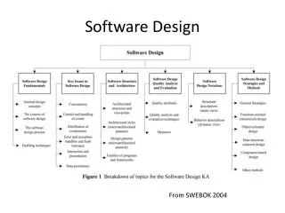
Swerve Drive Software Design. Software Layers. Joystick Axis Correction. Joystick Response Calculation. Motor/Wheel Orientation Adjustments. Field-oriented Angle Adjustment . Swerve Drive Steer Angle / Drive Speed Calculation. Drive Motor PID Controllers. Steer Motor PID Controllers.

E N D
Software Layers Joystick Axis Correction Joystick Response Calculation Motor/Wheel Orientation Adjustments Field-oriented Angle Adjustment Swerve Drive Steer Angle / Drive Speed Calculation Drive Motor PID Controllers Steer Motor PID Controllers L F R F L F R F L B R B L B R B
Software Tuning Motor/Wheel Orientation Settings Joystick Response Tuning Steering Angle Sensor Offsets Drive PID Tuning Steer PID Tuning P I P I D F D
Motor/Wheel OrientationNormalization • Steering Motors are mounted upside-down, Angle Sensors are mounted rightside-up. • Setpoint angles need to be inverted • Drive Motors are inverted on the left and right-side of the robot. • Some motors rotate “backwards” • Drive Motor Gear Ratios are not 1:1
Joystick Axis Correction • Flight Joysticks have Y forward as “dive”, so Y forward is NEGATIVE. • Drive Joysticks need to invert the Y axis.
Joystick Response Calculation • When Joysticks are at rest, they don’t read exactly 0 (in X, Y and Twist Axes). • A “deadband” is needed, otherwise the Robot will “twitch” when the joystick is centered. • Humans find non-linear joystick response (less-sensitive near the middle) easier to use. X/Y -> .4x^3+.6x Rot -> .7 * (.4x^3+.6x)
Field-Oriented Angle Adjustment • It’s simpler to drive an omniwheel system if joystick straight ahead is ALWAYS aligned with the field – even if the robot body is rotated. • It’s much simpler if rotating the robot doesn’t change the direction the joystick will move the robot. • Field-oriented drive reads the angular offset between robot’s current rotation and “north” on the field – using data from the IMU. • Then, software rotates the X/Y joystick directions by this difference.
Swerve-Drive Steer Angle/Drive Speed Calculation • Translates X, Y and Rotation Values into Steering Motor Angles and Drive Motor Velocities. • Steering Motor Angles are a “mix” of the X/Y angle, and a rotation angle (which is only present if Rotation != 0)
Steer Motor PID Controllers • Uses Angle Sensor (-180 to 180 degrees) as Input. • Outputs to Motors (-1 to 1). • Uses Proportional (P), Integral (I) and D (Differential) coefficients, which require tuning. • Operates 50 times per second. • Each steering motor has it’s own PID controller. • Fast, accurate operation is crucial to smooth performance.
Drive Motor PID Controllers • Uses RPM Sensor (360 ticks per revolution) as Input. • Outputs to Motors (-1 to 1). • Uses Proportional (P), Integral (I) and D (Differential) coefficients, which require tuning. • Operates 50 times per second. • Each drive motor has it’s own PID controller. • Required for high-accuracy autonomous “drive this far” commands, to ensure similar behavior at different battery levels, and to account for differing amount of wheel slip.
Joystick Response Tuning • Software adjusts the magnitude of the X, Y and Rotation values so it “feels” responsive to a human. • Autonomous code has no need for this correction. • This is an interactive process; here’s the curve that Lexa developed in the 2012 season for the mecanum robot. • We later adjusted this to slow down the robot we finally built, but unfortunately didn’t create a graph of this curve.
PID Coefficient Tuning • Simplest thing is P only. • If P doesn’t quite get there, we add an I. • If P overshoots, we can decrease P and increase D. • It’s not as easy as it sounds, and takes some time.