Download
1 / 22
230 likes | 388 Views
InAlAs/InGaAs/InP DHBTs with Polycrystalline InAs Extrinsic Emitter Regrowth. D. Scott, H. Xing, S. Krishnan, M. Urteaga, N. Parthasarathy and M. Rodwell University of California, Santa Barbara. dennis@umail.ucsb.edu 805-893-8044, 805-893-3262 fax. InP HBT Material Properties:

E N D
InAlAs/InGaAs/InP DHBTs with Polycrystalline InAs Extrinsic Emitter Regrowth D. Scott, H. Xing, S. Krishnan, M. Urteaga, N. Parthasarathy and M. Rodwell University of California, Santa Barbara dennis@umail.ucsb.edu 805-893-8044, 805-893-3262 fax
InP HBT Material Properties: Available lattice-matched materials allows for emitter bandgap wider than base, allowing for higher base doping and lower base sheet resistance Electron velocities reported as high as 4107 cm/s InP HBT Processing Technology : High topography mesa structure allows for small-scale integration Base-emitter junctions defined by etching and depositing a self-aligned base metal results in low yield and limits emitter scaling Si/SiGe HBT Material Properties: Allowable lattice mismatch limits Ge:Si alloy ratio resulting in smaller emitter-base bandgap difference and higher base sheet resistance 4:1 lower electron velocity is seen in silicon Si/SiGe Processing Technology : Planar process using silicon CMOS technology allows for VLSI Self-aligned base-emitter junctions are diffused, extrinsic base and emitter wider than the active junction allows for high degree of scaling Advantages of InP vs. SiGe HBTs
Evolution Cbc Reduction in III-V HBTs Emitter Emitter Collector Collector Base Base Subcollector Subcollector S.I. Substrate S.I. Substrate Mesa HBT Cbc Reduction HBT Emitter Emitter Collector Base Subcollector Collector S.I. Substrate Transferred Substrate HBT Highly Scaled HBT
UCSB Highly Scaled HBT • UCSB has demonstrated laterally • scaled HBTs with emitters written • by e-beam lithography. • These HBTs show problems with: • High emitter resistance, Rex • Low yield • These devices demonstrated lower than predicted values of fdespite aggressive thinning of the epitaxial layers.
Si/SiGe HBT Process Advantages • Highly scaled • very narrow active junction areas • very low device parasitics • high speed • Low emitter resistance using wide n+ polysilicon contact • Low base resistance using large extrinsic polysilicon contact • High-yield, planar processing • high levels of integration • LSI and VLSI capabilities Published Si/SiGe HBTf as high as 210 GHz InP-based HBTf as high as 341 GHz
Polycrystalline n+ InAs • Polycrystalline InAs grown on SiNx Hall measurements as high as: • Doping = 1.3 1019 cm-3, Mobility = 620 cm2/V•s • Results in doping-mobility product of 81021 (V •s •cm)-1 • Compare these numbers to InGaAs lattice matched to InP: • Doping = 1.0 1019 cm-3, Mobility = 2200 cm2/V•s • Results in doping-mobility product of 221021 (V •s •cm)-1 Polycrystalline InAs has potential as an extrinsic emitter contact!
Base-Collector Template for Regrown Emitter HBT Base-collector template prior to regrowth Base-collector template as-grown
Regrown Emitter Fabrication Process Regrowth Emitter/cap etch Metalization Base/collector etch
First Attempt Results Regrown area SiNx Regrown area very rough Transistor action!!
Growth and Process Improvements Regrown area Regrown area SiNx SiNx First attempt at the base- emitter junction without RHEED or pyrometer Second attempt with improved pre-regrowth processing and RHEED/pyrometer features added to the wafer
Growth and Process Improvements First attempt at the base- emitter junction without RHEED or pyrometer Second attempt with improved pre-regrowth processing and RHEED/pyrometer features added to the wafer
Base-emitter Regrowth SEM 2 μm emitter regrowth 30K magnification 1 μm emitter regrowth 55K magnification
Second Attempt DC Results • Unintended InAlAs Layer (>50Å) • wide-bandgap layer acts as a current block from emitter to base • reduces common-emitter gain • may account for the dip in common-emitter curves Common-emitter gain, β > 15
Base-emitter Current Leakage Evidence of resistance seen in the base-emitter diode Evidence of base-emitter leakage seen in Gummel
Third Attempt DC Results Third Attempt DC Results Common-emitter gain, β > 20
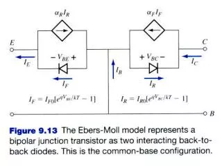
Base-collector Grade Design Error InP collector InP collector InGaAs base InGaAs base Base-collector band diagram with the incorrect base-collector grade. This mistake may account for the oscillations seen in the HBT I-V curve. Base-collector band diagram with the corrected base-collector grade. A thin, heavily-doped layer was inserted between the grade and collector to pull the conduction band down at the grade-collector junction.
InP HBTs with polycrystalline InAs extrinsic emitter regrowth Objective: • Emulate high-yield 0.2 um SiGe emitter process • Polycrystalline extrinsic emitter wide contact for low resistance Future Work: • RF devices need to be designed and demonstrated • GaAsSb based DHBTs should be demonstrated • Higher scaling in the regrown emitters needs to be examined Growth Related Work: • A low-resistance p-type polycrystalline contact needs to be verified • Regrowth of the base will need to be explored to obtain a fully planar HBT completely analogous to the Si/SiGe HBT
InP HBTs with polycrystalline InAs extrinsic emitter regrowth Objective: Emulate high-yield 0.2 um SiGe emitter process Polycrystalline extrinsic emitter wide contact for low resistance Future Work (short-term): Improve DC characteristics. Improve base capping layer to lower extrinsic base resistance GaAsSb base layers for higher carbon incorporation Deep submicron scaling of regrown emitter. RF device demonstration Future work (long-term): full SiGe-like process flow for submicron InP HBT regrown emitter, regrown extrinsic base over buried dielectric spacer for Ccb reduction
Future Work DC Device Work: • DC characteristics should be demonstrated without the design errors • Improvements will be made to the base capping layer to lower extrinsic base resistance • GaAsSb based DHBTs should be demonstrated • Higher scaling in the regrown emitters needs to be examined RF Device Work: • RF devices need to be designed and demonstrated Growth Related Work: • A low-resistance p-type polycrystalline contact needs to be verified • Regrowth of the base will need to be explored to obtain a fully planar HBT completely analogous to the Si/SiGe HBT