Download
1 / 15
150 likes | 258 Views
TOF for New-TPC experiment. Mizuki Sumihama May, 2 nd , 2008. Time-of-Flight Missing mass of single-K + , proton New-DC. Setup of forward. TPC New-DC DC1 DC2 DC3 TOF. Dipole. ~ 1 m. FWD(Plastic).

E N D
TOFfor New-TPC experiment Mizuki Sumihama May, 2nd, 2008 Time-of-Flight Missing mass of single-K+, proton New-DC
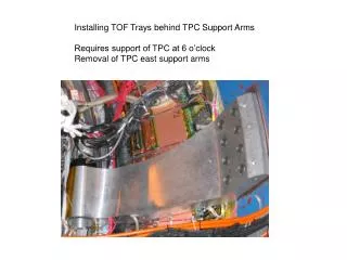
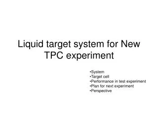
Setup of forward TPC New-DC DC1 DC2 DC3 TOF Dipole ~ 1 m FWD(Plastic) -1745 -830 -460 +1000 +3100 [mm] Momentum: No SVTX(SSD) , New-DC TOF : rf-TOF-wall , (Distance between target and fwd is ~1m.)
Tagger-Plastic counters for 2 nsec structure of RF signals Standard setup : We use Start counter to solve 2 ns ambiguity of RF signals. But New-TPC exp. : Distance between TGT and FWD is about 1m (too long!), and TOF between TGT and FWD is not negligible and difficult to solve the 2 ns ambiguity. Use tagger plastic counters
2 nsec structure in Tagger Before time-work correction After time-work correction 2 ns ambiguity can be solved by Tagger plastic counters
Mass spectra Few events not to solve 2ns-ambiguity.
Missing mass spectra ~5 days Eg < 2 GeV Eg < 2.4 GeV All n(p+) MM(K+) MM(p) Eg function up to 3GeV temporary determined by Kato w p0, h Require a hit in outers No signal of p0, h
Plots from the data with standard setup –Not any request at side region q<25 degree np0 h MM(K+) MM(p)
Z-vertex Target position q < 14 degree Polar angle for single track Vertex resolution for 2 track events is not good because of No SVTX(SSD) and small opening angles. improvement including New-DC ??
TOF with Tag-PL and Outers Front view of TDC, Inner and Outer • One-side readout for Inner • counters, time resolution is • about 800 ps by Yamamura. • Start timing is determined • by RF signals and solve 2 ns • ambiguity by Tagger-PL. • Stop timing is determined by • Outers. Time resolution is • about 200 ps by Yamamura.
b vs. momentum,dE/dx Information of path length, momentum and dEdx by Nakatsugawa-kun.
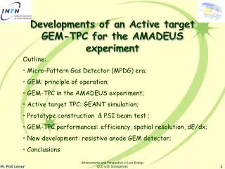
New-DC • Accept events go through forward. • Help to determine momentum vector • and vertex points in mixed magnetic field • of Dipole and Solenoid . TPC • Pitch 14 mm • YY’UU’VV’ 6 planes • U/V angle 30 degree • the same as DC2 and DC3 Forward LEPS New-DC Installation of NDC in program for side tracking (TPCana) is by Uchida.
Magnetic field New-DC ~0.1T ~0.05T
Cathode sheet (aluminized mylar) 12.5μm New DC DC0 V V’ U U’ Y 7mm Y’ 7mm 7mm 97mm sense wire (Au-W) φ30μm #50×6 Layer potential wire (Au-BeCu) φ100μm #50×6 Layer
xt-curve Expected hit position - Wire position Trace back from DC1 to each planes of NDC and determine initial xt-curve. iteration to have better xt curve. Solve left-right ambiguity By positions of fired wires In Y/Y’, U/U’ and V/V’. Require 6 hits in NDC. Y Y’ U U’ V V’
outlook Egamma calibration up to 3 GeV Alignment of New-DC Require hits in all 6 planes relax to 5 or 4 hits. The number of clusters in NDC is sometime huge. need a cut condition by an efficient /safety way Check run dependence of t0/xt-curve ………………..