Download
1 / 32
320 likes | 331 Views
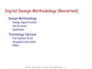
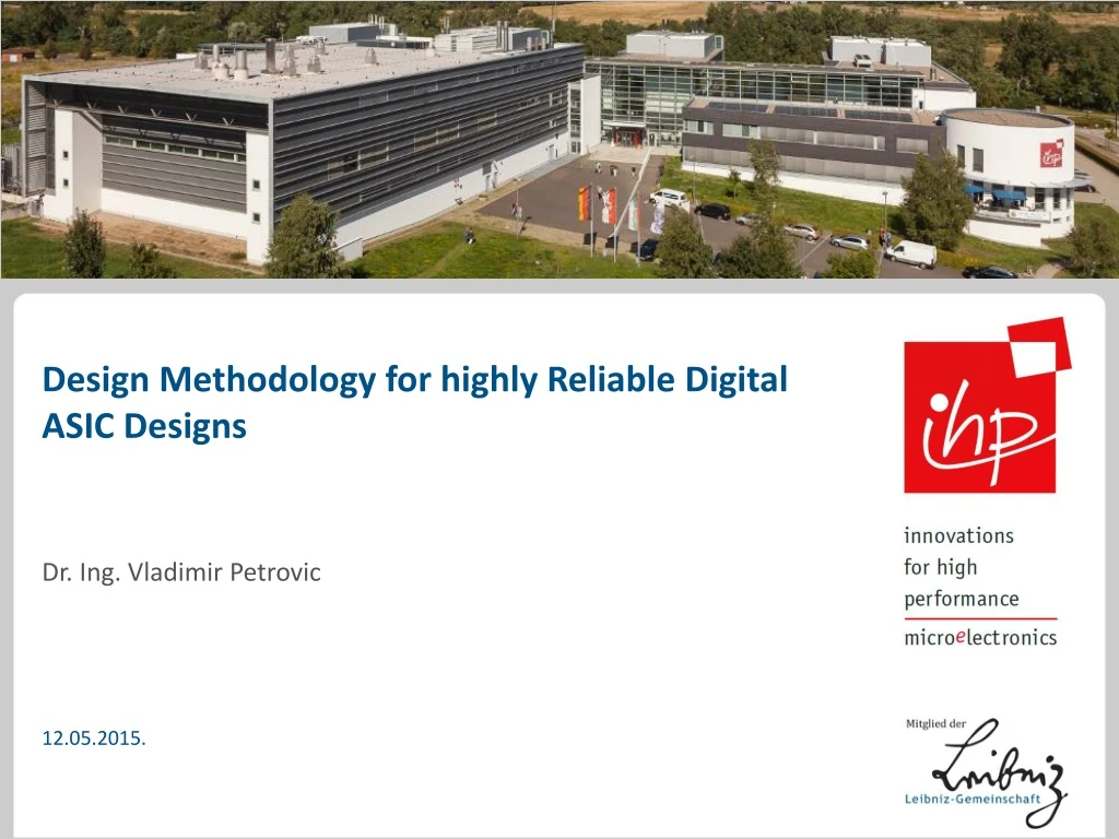
Design Methodology for highly Reliable Digital ASIC Designs. Dr. Ing. Vladimir Petrovic. 12.05.2015. Outlines. Motivation and goals Introduction Problems and potential solution Fault-tolerant circuits Modified design flow Implementation results Case study. Motivation and Goals.

E N D
Design Methodology for highly Reliable Digital ASIC Designs Dr. Ing. Vladimir Petrovic 12.05.2015.
Outlines • Motivation and goals • Introduction • Problems and potential solution • Fault-tolerant circuits • Modified design flow • Implementation results • Case study
Motivation and Goals • Dimension scaling and high integration of ICs increase the sensitivity to errors • Expensive radiation-hardened technologies are not attractive • Commercially available integrated framework that covers SEU, SET and SEL • Goal: Design flow for digital fault-tolerant ASICs which integrates • Commercially available tools • Standard processes • Fault-tolerant techniques
Introduction • Three main radiation sources in space: • The Solar wind • Cosmic radiation • Particles trapped in Van Allen belts Pictures source: http://www.nasa.gov/mission_pages/sunearth/spaceweather/
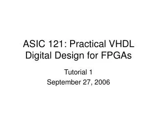
OUT GND IN VDD Introduction NMOS (M1) PMOS (M2) DP SN DN SP Metal Contacts P substrate P+ N+ N+ N well P+ P+ N+ Poly-Si Ie1 T2 Ic2 Ic2 Ic1 T1 Ie2 Ic1 R2 R1 SP (VDD) IE1 VDD T1 SP IC2 IC1 M2 T2 IN OUT IE2 M1 R1 SN SN (GND) GND Bulk Contact R2
Introduction • Radiation effects can be split in two general categories: Cumulative Effects Single Event Effects • Soft errors: • Neutron Single Event Upset (NSEU) • Single Event Transient (SET) • Single Event Upset (SEU) • Single Event Functional Interrupt (SEFI) • Ionization • Displacement (can also be caused by aging effects) • Enhanced low-dose-Rate Sensitivity (ELDRS) • Hard errors: • Single Event Latchup (SEL) • Single Event Gate Rupture (SEGR) • Single Event Burnout (SEBR)
Introduction • Radiation effects can be split in two general categories: Cumulative Effects Single Event Effects • Soft errors: • Neutron Single Event Upset (NSEU) • Single Event Transient (SET) • Single Event Upset (SEU) • Single Event Functional Interrupt (SEFI) • Ionization • Displacement (can also be caused by aging effects) • Enhanced low-dose-Rate Sensitivity (ELDRS) • Hard errors: • Single Event Latchup (SEL) • Single Event Gate Rupture (SEGR) • Single Event Burnout (SEBR)
Introduction • Almost all SEU and SET fault-tolerant techniques are based on the redundancy • Hardware redundancy (N-modular, triple and double modular redundancy) • Information redundancy (error detection and correction) • Time redundancy • Software redundancy
Problems and potential solutions • Problem: Full DMR circuit doesn’t correct error generated by SET during active clock edge • Solution: Additional logic in the voter feed-back line
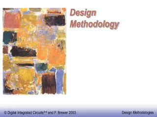
combinat. logic combinat. logic in_a D Q > voter voter out_a clk_a 1 0 1 0 in_b D Q > out_b clk_b Problems and potential solutions • Problem: Latchup protection is based on switching off the main power supply. The digital circuit logic states are in this case lost. • Solution: Latchup protection in combination with redundant circuits VDD GND SPS_a VDD_a SPS_b VDD_b
Problems and potential solutions New Design Methodology Redundant CircuitsModification Power Network Controller SEL Power Switch Design
Problems and potential solutions New Design Methodology Redundant CircuitsModification Power Network Controller SEL Power Switch Design
Fault-tolerant circuits • Modified DMR circuit
Problems and potential solutions New Design Methodology Redundant CircuitsModification Power Network Controller SEL Power Switch Design
Fault-tolerant circuits Main Power Supply • Protection switch is based on the Latchup Protection Technology (LPT) • Current driver is in the same time the current sensor • PMOS transistor with wide channel, used in the linear (ohmic) region • Current provided by the sensor/driver should be enough to supply several cells IM Main Chip Power Supply Current Sensor/Driver Control Circuit (part of SPS) Power Supply with High-Current Protection UDS Feed-back Control IS Standard Cells Power Network Connection
Problems and potential solutions New Design Methodology Redundant CircuitsModification Power Network Controller SEL Power Switch Design
Modified design flow • Power network controller (PNC) controls all latchup protection circuits (SPS cells) independently
Latchup protection cell • Layout modification is based on using free space under stripes for SPS placement
Latchup protection cell - Measurements • The radiation tests of SPS cells were performed at the Radiation Effects Facility at the Cyclotron Institute located on the campus of Texas A&M University – TAMU – in College Station, Texas (USA). • Tests were based on • SEU/SET tests with particle energies up to 50 MeVcm2/mg and • SEL tests in different temperatures and ion energies up to 74.8 MeVcm2/mg. • Ion cocktail used during radiation measurement was composed of different radiation sources: 4Ne, 40Ar, 63Cu, 84Kr, 141Pr, 181Ta, and 197Au. • Effective linear energy transfer (LET) was in range 2.6 MeVcm2/mg up to 82.8 MeVcm2/mg. • The SPS cell operated correctly during the all irradiation tests.
Case Study • Radiation hard library and special latchup protection cells which were successfully tested under irradiation
Case Study • Most important projects: • RTU-ASIC ICARUS • Middleware Switch Processor for internal satellite communication • VHiSSi • SEPHY (H2020 project)
Questions? • References: • [1] V. Petrovic, G. Schoof „Design Flow Approach for Reliable ASIC Designs“, NEXT 2010 • [2] V. Petrovic, M. Ilic, G. Schoof, Z. Stamenkovic “SEU and SET Fault Injection Models for Fault Tolerant Circuits”, BEC2012 • [3] V. Petrovic, M. Ilic, G. Schoof, Z. Stamenkovic, “Design Methodology for Fault Tolerant ASICs”, DDECS 2012 • [4] V. Petrovic, M. Ilic, G. Schoof, “Single Event Latchup Power Switch Cell Characterization”, YU SSSS 2012 • [5] V. Petrovic, M. Ilic, G. Schoof, Z. Stamenkovic, “Integrated Single Event Latchup Protection for ASICs used in Space Applications”, 21st TELFOR 2013 • [6] V. Petrovic, Z. Stamenkovic, M. Stojcev, T. Nikolic, G. Jovanovic, “Fault-Tolerant Reconfigurable Low-Power Pseudorandom Number Generator”, DDECS 2013 • [7] G. Schoof, V. Petrovic, S. Montenegro, “Systemarchitektur für Raumfahrtanwendungen”, 24th TUZ 2012 • [8] S. Montenegro, B. Vogel, V. Petrovic, G. Schoof, A. Herrholz, K. Gruettner, “Spacecraft Area Network (Scan) for Plug and Play of Devices”, PCC 2010 • [9] V. Petrovic, G. Schoof, Z. Stamenkovic, “Characterization and Verification of a Latchup Protection Switch in Radiation Environment”, Proc. of the Second International Conference on Radiation and Dosimetry in Various Fields of Research, 107 (2014), Serbia • [10] V. Petrovic, G. Schoof, Z. Stamenkovic, “Fault-Tolerant TMR and DMR Circuits with Latchup Protection Switches”, Microelectronics Reliability 54(8), 1613 (2014) • [11] V. Petrovic, G. Schoof, M. Krstic, “Verbesserter TMR-Strahlungsschutz für ASIC-Layouts”, Testmethoden und Zuverlässigkeit von Schaltungen und Systemen (TuZ 2015), Bad Urach, March 01 - 03, 2015, Germany DCPS 2015
Dr. Ing. Vladimir Petrovic 357 671
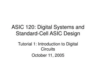
Problems and potential solutions • TMR vs. DMR failure-free probability TMR circuit DMR circuit DCPS 2015