Download
1 / 30
300 likes | 416 Views
HFT Geometry Considerations. F.Videbæk BNL. Introduction. This presentation is meant to be a living document, updated as more and better information becomes available. Version 2 December 9, 2011. Support Structure Overview. Schematic Layout. Current Geant View courtesy Spiros. As build.

E N D
HFT Geometry Considerations F.Videbæk BNL
Introduction • This presentation is meant to be a living document, updated as more and better information becomes available. Version 2 December 9, 2011
Supporting StructuresXY cut OSC (r=21 cm) PST ~13 cm Beam Pipe
Details on cylinders • OSC Outer Support Cylinder • CF ~ 800 micron; • Will support SSD for run14+ • PST (Pixel Support Tube) • Isolate PXL from other part. Enables cooling of PXL • Install for engineering run 13. • Will support IST from run-14+ • CF ~ 800 Micro
Pixel Support Tube • SW model
OSC Flange Diameter 432.4/2 Diameter 435.4/2
Material and Radiation Lengths • OSC: • The nominal thickness is 1mm (cross check) of CF. The precise rd. length of CF depends on the compositions but is usually around 24 cm. • Thus 1 mm <-> 1/240= 0.42 % rad length • MSC (PST) • 800 microns = 0.33%
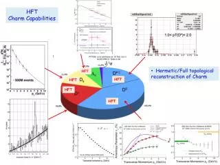
PXL material budget • The nominal average thickness is 0.37 rad length (for Al based cable) , but is clearly large at sector beam sides. • Also the ladders are not perpendicular so incident angle goes from ~90 deg to ~ 60 deg. For the inner sector; slightly slanted for outer sector.
Beam Pipe material • Assume the Beam Pipe is Be with a thickness of 0.8 mm, and an outer radius of 20 mm. • Q: Have the as built dimensions been checked.
IST material • The TDR claims ~ 1.1% overall. It would be important to look at the budget in the Si/CF foam area and in the APV/cooling tube area separately.
SSD material • This should be accounted for in the current GSTAR, but also in the NIM article.
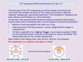
PXL ladder and support beam structures. • First input is to understand the Sector layout and get it into GSTAR to study phi variation of radiation length, not just averages.
sector geometry based on ladder layout ph1.SLDPRT (Sketch2) The outer ladder positions are defined by placing the active edge of the pixel array (side opposite pad row) on an 80 mm radius and positioned 12 mm apart. The starting point for the first active region is placed 0.7885 mm from the vertical surface of the sector beam along the surface line of the active silicon. The side surfaces of the sector beams are defined by lines 1 mm inside and parallel to the vertical radial line and the 36 deg radial line. The ladder angle is defined by requiring a 1 mm overlap of the active regions for the phase 1 detector
sector geometry based on ladder layout ph1.SLDPRT (Sketch2) The grey rectangles have the length of the active region of phase 1 detector and the thickness represents what was expected to be the ladder thickness. This is what is used to define the sector beam surface that the ladder gets bonded to. The ladder thickness ended up slightly different than the value here of 0.7716 mm, so the ladders will be off a little from the 80 mm radius circle.
sector geometry based on ladder layout ph1.SLDPRT (Sketch2) The inner ladder is positioned with the active edge next to the wire pads on a 25 mm radius circle. The angle is defined by a 1 mm overlap of the active region. There is an arbitrary offset from the sector beam side edge.
sector beam ph1.SLDPRT (Sketch1) The sector beam shape is linked to ladder layout ph1.SLDPRT (Sketch 2) The 6 longer straight lines are collinear with the inside rectangle edges. All the arcs but one have a 1.5 mm radius . All arc are tangent to joining lines. The 2 short lines are collinear with radius lines. 3 points are coincident with points in ladder layout ph1.SLDPRT (Sketch 2). This completely defines the shape. The beam material extends in from the sketch. 1 2 ladder layout ph1.SLDPRT 3
The actual placement of the ladders in the model deviate a little from the ladder layout ph1.SLDPRT because the ladder thickness is not quite as specified in the layout. ladder layout thickness: 0.7716 mm ladder model thickness: 0.8716 mm
Approach • Got all information from Howard how the geometry in SW is setup. • Check with SW model. Extracted other info from there. • Put this information into a root script that could generate cross section of geometry. i.e. picture from last week. • Generated root Tgeo script that could be executed to generate geometry. See next two slides for output. • Communicated with Jonathan and Jason
Scripts • The scripts are currently in ~videbaek/star (i.e. my BRAHMS area- since I use root v5.28 for daily work). • Sector.C • Calculates based on general information the detailled information need to make the cross section plot and output Root TGeo.. Statements • assembly.C • Embedded output from above program and executes a root macro the generate the root geometry, and draw this.
Sector ladder layout Active Si (19.2*19.2 mm) 12.6345 cm 39.745 cm (CF beam) Cable Length 33.447 cm ~20 cm