Download
1 / 13
130 likes | 225 Views
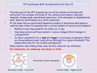
HFT-prototype BUR considerations. (Quantitative) What physics is possible in Run-13 assuming some (prototype) sectors are there? Relates to how long would be the AuAu run How many sectors will be build -> can we change/afford changes in configuration?

E N D
HFT-prototype BUR considerations (Quantitative) What physics is possible in Run-13 assuming some (prototype) sectors are there? Relates to how long would be the AuAu run How many sectors will be build -> can we change/afford changes in configuration? Is there a possibility for a high pt trigger in prototype acceptance? (patch EMCal) to enhance Rcp at higher pt. What are the peripheral event (limiting), error defining rates for a given threshold? This makes sense only for the Joined-configuration Need realistic data-taking rates, duty factors, detector ‘up’ estimates This is a project question NOT just a software exercise.
ASSUMPTIONS: Only 3 PXL sectors will be installed (reality: 0-4 will be build) To first-order Ghosting is not affecting combinatorial background (~N2, N = #tracks in TPC with HFT hits) or S/B [if we require tracks to have HFT hits]. There will be second order, cut dependent effects though. Here we account for loss of signal due to ghosting (% loss of efficiency). For now we can rely on Yifei’s CDR plots adapted/scaled for partial coverage using Jonathan’s acceptance/single-track-efficiency (with pileup) results. http://www.star.bnl.gov/protected/lfspectra/yfzhang/hft/plots/CDR/ Single track efficiency (STE) changes about ~10% for all pt (from 70%->60%, see fig below), so impact on D0 signal is ~15% (or multiplication factor .85) For Mercedes/Joined configuration we have geom. acceptance penalty for D0s Handwave estimation (3/10)2 = ~ 10% @ sweet spot of pt=1 GeV/c for Mercedes and 10% for pt=5 GeV/c in Joined configuration only. In all other pt one needs to read the STE and ACC curves. Realistic/GEANT estimation from Jonathan see plots below, but about the same. Yifei’s estimates of efficiency (= STE plus acceptance) (see fig-3 CDR and below) are about the same Hao will pin this down precisely
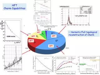
HFT-prototype BUR considerations Rough estimates: For 500 Million AuAu 200 GeV events (CDR plot input) The pt, and v2, plot errors should be increased @ 1 GeV only pt by a factor of 3-4 for the Mercedes prototype, and the same factor @ 5 GeV for the Joined prototype. This number results from evaluating the signal error (sqrt(S)) with the new penalties in track efficiency and acceptance combined for these two sweet spots. The number increases rapidly for lower/higher pt (Mercedes) and lower pt (Joined). See full acceptance plots below for details. The above estimate is based on simulations with ideal TPC. For a more realistic approach with a TPC with distortions the factor to increase the errors is 6-7 !! This is mainly due to sharp drop in TPC+PXL track matching efficiency.
Jonathan’s single track efficiency detailed PROTOTYPE • Curves are for ALL particle species • Red point are closer to real pileup
Jonathan’s single track ghosting detailed PROTOTYPE • Curves are for ALL particle species • Red point are closer to real pileup
Jonathan’s acceptances Mercedes -3 Joined-3 See next slide for % (ratio) plots
Jonathan’s acceptances detailed |h|<0.5 Indeed sweet spots are about 10%
Fig-5 CDR Estimated errors for ideal, realistic TPC Fig-8 CDR
Summary • Depending on events on tape AND # of sectors available AND %-detector alive AND … we should be able to get a x-section and a RCP estimate • Need detailed input, simulation studies • Unfortunately many critical factors are still undefined