Download
1 / 16
170 likes | 279 Views
NON-EQUILIBRIUM HEAVY GASES PLASMA MHD-STABILIZATION IN AXISYMMETRIC MIRROR MAGNETIC TRAP. A.V. Sidorov 2 , P.A. Bagryansky 1 , A.D. Beklemishev 1 , I.V. Izotov 2 , V.V.Prikhodko 1 , S.V.Razin 2 , V.A. Skalyga 2 and V.G. Zorin 2.

E N D
NON-EQUILIBRIUM HEAVY GASES PLASMA MHD-STABILIZATION IN AXISYMMETRIC MIRROR MAGNETIC TRAP A.V. Sidorov2, P.A. Bagryansky1, A.D. Beklemishev1, I.V. Izotov2, V.V.Prikhodko1, S.V.Razin2, V.A. Skalyga2 and V.G. Zorin2 1Budker Institute of Nuclear Physics, 630090, Novosibirsk, Russia 2Institute of Applied Physics, 603950, Nizhny Novgorod, Russia
ECR Multicharged Ion Sources Applications Accelerator injectors Technologies Hadrontherapy Heavy Ion Fusion Beta beam project Surface processing Ion implantation (SOI-technologiesetc) High density energy physics
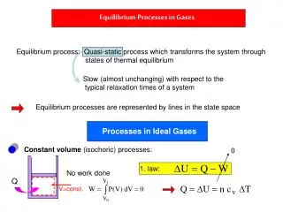
Principles of Gas-dynamic ECR Ion Source Operation Magnetic trap, 2 T, R=5 U~30 kV Plasma electrode (PE) SMIS 37 FC Gyrotron radiation 100 kW @ 37.5 GHz Puller ECR discharge beam Np~Ncutoff~1013cm-3 Te~70eV Lp~30 cm High e-i collision frequency L~35 cm Loss cone is filled Gas-dynamic regime of confinement EDF is isotropic λii<<L τc=1/νei << τg=Leff/Vs Plasma lifetime = τg
Minimum-B field Confinement in ECR Ion Source Solenoid Coils Sextupole e- heating µ wave gas ions
MW Ion beam Ø 1 mm N: <Z>=2 Ag: <Z>=3.5 Magnetic coils MHD stabilization: Cusp-type magnetic configuration Losses trough the axial slit is too high!
GDT experiment parameters(D-beams, Н – plasma) • Plasma density: 1.531013cm-3 • Electron temperature: 140 eV • Hot ions density: 41013cm-3 • Center magnetic field: 2.83 kG • D-injection power: 3.5 MW • Trapped power: 2 MW
Limiter (+150 V) Plasma source Injection +150 V Plasma receivers V Injection V V V V cm Vortex confinement: potential profile control Potential profile β ~ 0.6!! E. I. SOLDATKINA, P. A. BAGRYANSKY and A. L. SOLOMAKHIN. Plasma Physics Reports, 34, 259 (2008).
- ion gyroradius, L– trap length,a – plasma radius. Atm=1 mode dominates in spatial spectrum of the flute instability Finite larmor radius (FLR) effect GDT SMIS 37 Ion beam emittance ~ , so in ECR ion sources ion temperature is low, 1÷10 eV and FLR effects are negligible.
Vortex confinement: theory • Calculation results (A. D. Beklemishev) Calculatedenergy life-time changingin SMIS 37 setup for heliumplasma. Times normalized on the time of external layers turning according to internal layers.Initial unperturbed state of the plasma cord (time=0) was chosenaxisymmetric with the symmetry center equal to the magnetic system center.τE=50 correspond to the gas dynamic confinement time. In case of the absence of the shear flow τE=5. A.D.Beklemishev, Shear Flow Effects in Open Traps, Theory of Fusion Plasmas, AIP Conference Proceedings 1069 (2008) pp.3-14.
Magnetic field coils Limiter Zonds MW 100 kW@ 37.5 GHz Isolators Discharge vacuum chamber Expanding chamber Edge magnetic force line Scheme of the experiments
Total charge registered by zonds #1-3, Helium Magnetic field at the plug: 1.7 T 1 2 3 zonds #1-3
Total charge registered by zonds #1-3, Nitrogen Magnetic field at the plug: 1.7 T Critical value of the U limiter in both cases is about of 70 V what is close to electron temperature and it is in good agreement with calculations
Mode structure: calculations and experiment Plasma potential and electron temperature distribution in the plasma cord section. Potential is normalized on the electron temperature; 1 – corresponds to limiter radius projection in central plane of the trap. Calculations show that azimuthal modes m=1, m=2 and m=3 have to dominate in the spatial spectrum under conditions of “vortex” confinement. Experiments show that azimuthal modes m=1 and m=2 dominate in the spatial spectrum under conditions of “vortex” confinement what is in good agreement with calculations.
“Decay” experiment: microwave pulse-length 400μs Limiter voltage Ulim=150 V Limiter voltage Ulim=0 V End of the microwave pulse Ion saturation current on the center zond (#1)
Future plans The experiments demonstrated good agreement with calculation: mode structure, critical value of the limiter potential for “vortex” confinement regime realization In future it is planned to improve electrode-limiter for the opportunity to control the potential profile and to extract the ions from the plasma at the same time. In this case it will be possible to research multicharged ion creation in the plasma of ECR ion source under conditions of “vortex” confinement regime realization.