Download
1 / 42
640 likes | 1.19k Views
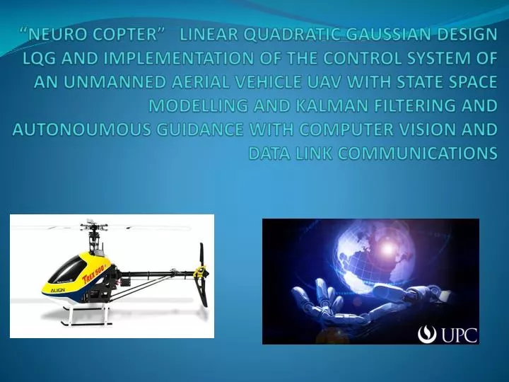
“ NEURO COPTER” LINEAR QUADRATIC GAUSSIAN DESIGN LQG AND IMPLEMENTATION OF THE CONTROL SYSTEM OF AN UNMANNED AERIAL VEHICLE UAV WITH STATE SPACE MODELLING AND KALMAN FILTERING AND AUTONOUMOUS GUIDANCE WITH COMPUTER VISION AND DATA LINK COMMUNICATIONS. MECHATRONIC TEAM.

E N D
“NEURO COPTER” LINEAR QUADRATIC GAUSSIAN DESIGN LQG AND IMPLEMENTATION OF THE CONTROL SYSTEM OF AN UNMANNED AERIAL VEHICLE UAV WITH STATE SPACE MODELLING AND KALMAN FILTERING AND AUTONOUMOUS GUIDANCE WITH COMPUTER VISION AND DATA LINK COMMUNICATIONS
MECHATRONIC TEAM The Mechatronic Team has the main objective for the development project to make the electromechanical integration of the acquisition, actuators and power systems of an Unmanned Aerial Vehicle UAV, and also do the respective flight test. Therefore, it is required to make a careful selection by engineering criteria of both the vehicle and the electronic components on board that will allow us to achieve the established objective of obtain an autonomous vehicle useful for multiple applications. ABSTRACT
MECHATRONIC TEAM • Tasks • Selection of components: vehicle, sensors and actuators • Design of electronic board: Control Power Servo Drives, Acquisition of PWM signals and micro controller QE128. • Freescale QE 128 Programming. (microcontroller). • Flight test: Data Capture of sensors and actuators. • Neuronal control and system identification.
Freescale µController QE128 Programming • ADC interfaces. • Serial Communication interface. (Tx & Rx) • PWM modules: PWM signal generation, and capture of PWM signals. • SPI protocol (Master – Slave): SD memory in SPI mode. • Flight algorithms.
Flight test: Real Time Data Capture of sensors and actuators. PWM and sensors Capture Conversion of digitized data tounits of measurement data KalmanFilter System ID
Neuro controller for a MIMO system ID Inputs: accelX: Linear Acceleration axis X ( m/s2). accelY: Linear Acceleration axis Y ( m/s2). accelZ: Linear Acceleration axis Z ( m/s2). GyroX: Angular velocity axis X (°/sec). GyroY: Angular velocity axis Y (°/sec). GyroZ: Angular velocity axis Z (°/sec). AngX: Angle X in degrees °. AngY: AngleY in degrees °. Height:Height of the helicopter from the land in centimeters. Outputs: u1: % PWM DutyCycleMain Rotor. u2: % PWM DutyCyclePitch Servo. u3: % PWM DutyCycleRoll Servo (Rightside). u4: % PWM DutyCycle Roll Servo (Leftside). u5: % PWM DutyCycleYaw Servo. Neuro controller: MLP network model is used. The design of the NN is composed by 9 values at the input layer, 10 activation sigmoid neurons at the hidden layer, and 5 linear neurons at the output layer. The training is done by the backpropagation algorithm of the NN Matlab toolbox.
Training Results: Real PWM VS Neuronal PWM Main rotor velocity: Pitch servo:
Roll servo (Rightside): Yaw servo: Roll servo (Leftside):
CONTROL The development of autonomous scale helicopters responds to the need for greater flexibility, agility and simplicity of operation. However, they present highly nonlinear flight dynamics and also they have high sensitivity to control inputs and disturbances. If we add the fact that helicopters present different characteristics for each flight mode, the development and implementation of an intelligent control system becomes a critical factor for the deployment of this kind of air vehicles.
CONTROL STAGES • SystemIdentification • LQG controllerdesign • Neural Network design
System Identification • ax • ay • az • p • q • r • h • Input Data • Output Data • HELICOPTER • Black Box We used the method of Linear Regression with Least Squares using QR decomposition to approximate the real system to a transfer function. Transfer function of order “m”: Rewriting the equation above and adding an error term representing the difference between the real system and approximate system, the linear regression model is obtained: • Error Term • Output DataAvailable • Regression • Vector • Unknown • Parameters s
System Identification According to the least squares sense, it is necessary to minimize: A method of estimating the unknown parameters in a way to reduce the square error is through Linear Regression with Least Mean Square Estimation using QR decomposition Knowing that: Where ‘p’ is the number of unknown parameters The matrix can be separated in an orthogonal Q matrix and in an upper triangular R matrix using the command (QR).
Linear Quadratic Gaussian Controller (LQG) LQG LQE LQR LQE (KalmanFilter): An optimal estimator for estimating the states in the presence of AWGN noise. LQR: An optimal regulator supplied by estimated states (LQE) which are taken to zero. • Noise measured by sensors • Exogenous disturbance • Component degradation
Linear Quadratic Gaussian Controller (LQG) • Diagram of LQG controller: Exogenous disturbance Noise measured by sensors • Optimal Estimator(LQE) • Optimal Controller(LQR) + • KalmanFilter LQG
Neural Network Controller The neural network controller tries to identify the controller K obtained by the Linear Quadratic Regulator LQR method. It is important to notice that the inputs to the neural network are the outputs of the Kalman filter. W1 W2 u XO Configuration: y- y h- h+ Linear Neurons Nonlinear Neurons
Neural Network Controller The algorithms for updating the weights is the Backpropagation which involves the development of partial derivatives. Learning Algorithm: It is necessary to establish a Quadratic Cost Function in order to penalize the error and reduce the energy that is coupled to the system
Neural Network Controller Exogenous disturbance • Final Diagram: Noise measured by sensors • Neural Network W2 W1 • Optimal Estimator(LQE) + • KalmanFilter LQG
COMPUTER VISION ABSTRACT Computer vision is a field of artificial intelligence, which objective is to program a computer in order to “understand” a scene or characteristics of a certain image. A common problem in airports is the presence of birds that blocks the aircraft takeoff. Another common situation is the lack of a fast and movable surveillance system. That’s why we propose an affordable, easy to use, modular system with three operation modes.
Abstract • Tracking mode. The Neurocopter is able to follow a certain object within its vision range • All weather vision.In addition for the Tracking Mode this Mode allows enhance the image for poor or excessive light situations • Bird Detection. It allows us to identify bird in the scene.
Tracking Mode • We explore the following pre-processing algorithms: • Mean filter • Median filter • Morphological filters (Opening, Closing, Filling Holes and Clear Border)
Tracking Mode • The segmentation algorithm was implemented in a Nvidia GTX 465 video card exploding its parallel processing technology. It gave us a reduction of 55.7% in time of execution. • Euclidean distance
All Weather Vision • This mode was achieved using the Gamma Correction which consists in a non-linear adjust of the brightness or luminance on an image. For the darkest pixels the brightness is highly increased while the brightness for the clearest pixels is increased in an minor amount. As a result more details are visible on the image.
All Weather Vision • The gamma correction was implemented on the GPU because most of the operations include matrices, this allows us to take advantage of the parallel processing. Gamma NightVision = 0.9 Gamma Sun Block = 1.03 • Time CPU • 0.0159 • Time GPU • 0.0028 • Reduction of 82.4%
Bird Detecction Thresholding: It’s about defining a threshold which separates the objects from the background. It is useful only if there is a clear difference between the objects and the background of the scene.
Bird Detection • Threshold = 0.3 • There is no need to use elaborated algoritms like the Otsu algoritm
DATALINK ABSTRACT The purpose of these project is to solve the communication problems and to ensure the control of the helicopter and its monitoring. Some problems may happen in the communication system due to limitations like electromagnetic interference, loss of communication link, errors in transmission or capture of wrong information.
DATALINK-ABSTRACT The principal objectives are: • To select the technology for the communications system which satisfied to the required specifications. • To design a software when can monitoring the data transmitted ( altitude, orientation and speed) • To display the absolute position of the vehicle through the GPS scale
DatalinkDiagram 1. Datalink Up 2. Datalink Down 3. TCP Protocold GCS (Server) Control (Client)
ACTIVITIES • Choose a communication device and configure and test it. • Simulate data acquisition of the sensors and GPS in order to evaluate the software developed. • Display information received from the helicopter to the base station.
MONITORING BY GOOGLE EARTH Start of Google Earth No Receive GPS data? Yes Extract latitude, longitude KML record Show flight and UAV position Finish? No Yes End
SERIAL PORT COMMUNICATION Start 1 State: Data received Configuration of the serial port parameters No Finish data sending? Open serial port Yes State: Finish Receive VC frame? No Close serial port Yes Send ACK frame End Prepare to receive No Data? Yes 1
SERIAL PORT COMMUNICATION Start 1 State: Send Data Configuration of the serial port parameters No Finish data sending? Open serial port Yes Send VC frame State: Finish Receive VC frame? No Close serial port Yes Prepare to receive End 1
XML AND KML • XML, acronym for Extensible Markup Language . It’s an extensible meta tags developed by the World Wide Web Consortium (W3C) • XML is not born only for use internet, it is proposed as a standard for exchanging structured information between different platforms. It can be used in databases, text editors, spreadsheets and almost anything imaginable. • KML is a markup language and its used to represent data in three dimensions.
KML PROGRAMMATION • KML Programmation <xml version <kmlxmlns=“…” <Placemarks> <name> … </name> <description>….. </description> <point> <coordinates> Latitud,longitud,altura </coordinates> </point> </Placemarks> </kml>
Conclusions. • The mathematical analysis allows a comprehensive understanding of the system to be developed: Place a scale helicopter called “Neuro Copter” prototype in a state of "Hover." • Given the cost numbers and physical dimensions of the prototype to implement, was determined to take safety measures for the first flight test, using a security system comprised of harness, and a safe landing. In addition, convenient saw the acquisition of a prototype low-cost training in comparison to the final model for the respective flight test and flight training. • As a way of alleviating the computational burden of the Control Team and the Vision Team was chosen to perform each of the two processes on different computers. We created a client-server application TCP / IP to communicate between computers. • The GCS is an important tool that will serve as interface man - machine for controlling the UAV. This software will change in real time between each of the navigation modes are available: Collision Avoidance, Navigation and Waypoint Day / Night Vision. • The GCS will allow real time viewing of both the position of the UAV and its speed, angular acceleration, height and other states. In addition, you can display the battery status is making contingency alert to be issued. • The image processing is strongly improved by the use of parallel processing tecnology provided by the graffic card. • The Linear Regression with Least Squares using QR decomposition is more efficient that using pseudo-inverse and, also, this last method does not always provides a consistent solution for estimating the unknown parameters. • The Linear Quadratic Gaussian Controller allows the track of all the states even if they are contaminated by AWGN noise. • The estimated level of system identification using neural networks using the MLP model is vastly superior to the estimation using the autoregressive model ARX. • Neural networks are highly recommended for system identification and development of controllers for nonlinear systems. • For the training is recommended to leave 20% of the information to make the neural network able to generalize. • Once, the neuro controller is trained, it is necessary to validate the neural network. For example, feed to the system with different values to the training patterns and verify that the output is consistent. • Leave a small margin of error on the training goal (non-zero error) in order to allow the network to generalize. • For the modeling of the system take advantage of neural networks, and decompose the system into simple elements. • The torque of the helicopter is 1, 0115 Kg.m.