Download
1 / 22
610 likes | 1.47k Views
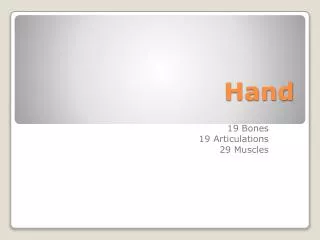
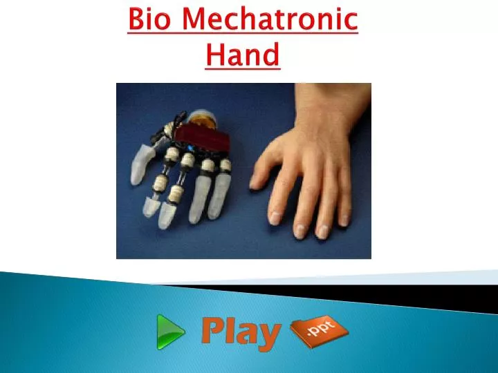
Bio Mechatronic Hand. INTRODUCTION. The objective of the work of an bio mechatronic is to develop an artificial hand which can be used for functional substitution of the natural hand (prosthetics) and for humanoid robotics applications .

E N D
INTRODUCTION • The objective of the work of an bio mechatronic is to develop an artificial hand which can be used for functional substitution of the natural hand (prosthetics) and for humanoid robotics applications. • The artificial hand is designed for replicating sensory-motor capabilities of human hand. • Commercially available prosthetic devices, such as Otto Bock Sensor Hand, as well as multifunctional hand designs are far from providing the grasping capabilities of the human hand.
INTRODUCTION • In prosthetic hands active bending is restricted to two or three joints, which are actuated by single motor drive acting simultaneously on the metacarpo-phalangeal (MP) joints of the thumb, of the index and of the middle finger, while other joints can bend only passively. • This limitation in dexterity is mainly due to the very basic requirement of limited size and weight necessary for prosthetic applications. • On the other hand robotics hands have achieved high level performance in grasping and manipulation, but they make use of large controllers which are not applicable in prosthetics or humanoid robotics where it is necessary to provide the user with a wearable artificial hand.
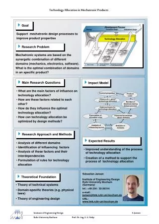
BIO MECHATRONIC design • The main requirements to be considered since the very beginning of a artificial hand design are the following: natural appearance, controllability, noiselessness, lightness and low energy consumption. • These requirements can be fulfilled by implementing an integrated design approach aimed at embedding different functions (mechanisms, actuation, sensing and control) within a housing closely replicating the shape, size and appearance of the human hand. • This approach can be synthesized by the term: “biomechatronic” design.
Architecture of the biomechatronic hand • The biomechatronic hand will be equipped with three finger to provide a tripod grasp: two identical finger. • The finger actuator system is based on two micro-actuators, which drive the MP and the PIP joints respectively; for cosmetic reasons, both actuators are fully integrated in the hand structure: the first in the palm and the second within the proximal phalange. • The grasping task performed by the biomechatronic hand is divided in two subsequent phases: 1) Reaching and shape-adapting phases; 2) Grasping phase with thumb opposition.
Architecture of the biomechatronic hand Fig. : Architecture of the biomechatronic hand
The actuation system • The adoption of bulky and heavy actuators, in the design of commercial upper limb prosthesis, lead to an extreme reduction of DOFs. • Consequently, a stable grasp can be achieved by means of high grip forces. • Starting from this viewpoint we are developing an artificial hand actuated by micro-drives. • Due to its enhanced mobility our hand will be able to increase the contact areas between phalanxes and grasped object. • Following this basic idea we can accept a reduction in power actuation increasing contact areas in order to augment grip stability.
The actuation system Fig. : Novel approach loop
INDEX/MIDDLE FINGER DESIGN • The two prototypes have been designed by reproducing, as closely as possible, the size and kinematics of a human finger. • They consist of three phalanxes and of palm housing, which is the part of the palm needed to house the proximal actuator.
INDEX/MIDDLE FINGER DESIGN Fig. : Index/Middle finger
THUMB DESIGN • A thumb has been designed in order to complete the hand prototype and to perform grasping tasks with thumb opposition. • The thumb has been designed by simply removing the distal phalanx from the index/middle finger
THUMB DESIGN Fig. : Thumb
HAND ASSEMBLING AND FABRICATION • A first prototype of the hand has been developed incorporating two fingers and thumb. • In fact, at least three hard-fingers are necessary to completely restrain an object. • The assembling process allows the hand prototype to perform two grasping tasks. 1. Cylindrical grasp 2. Tripod pinch grasp • The hand prototype has been fabricated using the Fused Deposition Modeling [FDM] process.
HAND ASSEMBLING AND FABRICATION Fig. 7: Pictures of cylindrical and tripod grasps
HAND ASSEMBLING AND FABRICATION Fig. 7: Pictures of cylindrical and tripod grasps
FINGERTIP FORCE CHARACTERIZATION • A first set of experimental tests has been performed in order to evaluate the force that the index/middle finger is able to exert on an external object. • To this aim we have measured the force resulting when the finger is pressing directly on a force sensor corresponding to different configurations of the joints. • Two “pressing” tasks were identified in order to evaluate separately and independently force obtained by the two actuators incorporated in the finger: TASK 1: the pushing action was exerted only by the distal actuator. TASK 2: the pushing action was exerted only by the proximal actuator.
POSITION SENSOR • Six position sensors, based on Hall-effect sensors (SS495A, Honeywell, USA), has been integrated in the hand structure in order to measure the angular position of the six active joints. • The main advantages of Hall-effect sensors are their small size and their contactless working principle, which allow us to avoid friction forces. • In the MP joints, the sensor measures a linear movement of 5.2mm; in the PIP joints, the linear movement is 8mm.
POSITION SENSOR (a) Slider for the MP joint. (b) Slider for the DIP joint. Fig. : Drawings of the two position sensors (the dimensions of (a) are 12x4x8 mm3, and the dimensions of (b) are 8.7x4x6 mm3).
POSITION SENSOR Fig. : The first prototype with the 2 integrated sensors.
FUTURE IMPROVEMENTS • The experimental tests showed promising results, but there is still room for improvement. • First of all, natural fingers movements during grasping activities will be further investigated in order to achieve a truly “human-like” behavior of the artificial finger. • The force sensor measurements will be further investigated in order to sense incipient slippage and to obtain force sensing abilities. • Finally, suitable control strategies will be investigated and applied in order to develop a natural control of the wearable hand.
CONCLUSION • It is based on integrating together multiple degrees of freedom, multi-sensing capabilities, and distributed control in order to obtain “elegant” human-like appearance, simple and direct controllability, low weight, low energy consumption and noiselessness. • Following this type of approach a firsthand prototype with six DOFs has been designed and fabricated. • In this paper we focused our attention on the design and development of a first implementation of an innovative hand, and in particular on the biomechatronic approach and on the integration of the position and force sensors.
Thank You www.playppt.com