Download
1 / 23
250 likes | 471 Views
Distributed and Reconfigurable Architecture for Flight Control System. EEL 6935 - Embedded Systems Dept. of Electrical and Computer Engineering University of Florida. Liza Rodriguez Aurelio Morales. Outline Introduction State of the Art: Airbus FCS Massive Voting Architecture

E N D
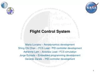
Distributed and Reconfigurable Architecture for Flight Control System EEL 6935 - Embedded Systems Dept. of Electrical and Computer Engineering University of Florida Liza Rodriguez Aurelio Morales
Outline • Introduction • State of the Art: Airbus FCS • MassiveVotingArchitecture • Modeling and Simulation • Conclusions
Outline • Introduction • State of the Art: Airbus FCS • MassiveVotingArchitecture • Modeling and Simulation • Conclusions
Flight Control Systems • Initially : Mechanical • Heavy, uses systems of pulleys, cranks, tension cables and pipes • Now: Fly-by-Wire • replaces manual control of the aircraft with an electronic interface • movements of flight controls are converted to electronic signals • flight control computers determine how to move the actuators at each control surface to provide the expected response
System Requirements • General Aviation Safety • Operational reliability, high performance, energy efficiency, low cost • Dependability • Integrity – must not output erroneous signals, should not send incorrect information to actuators • Availability – system must always be available to process requests • Radiation • Can cause over voltages and under voltages • Electromagnetic radiation should not affect data communication • Indirect effects of lightning is a possible source
Outline • Introduction • State of the Art: Airbus FCS • MassiveVotingArchitecture • Modeling and Simulation • Conclusions
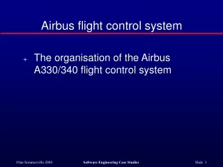
State of the Art: Airbus FCS • FCS is based on self checking flight control computers • System functions are divided between computers so that only 1 FCC is active at a time and the others are standby • Computers control each actuator with priority order, thus loss of a single computer does not mean loss of a particular function • System can run using only 1 FCC if necessary • Error checking is performed by 2 units of FCC • Command & Monitoring - both units have the same inputs and calculate the same outputs • If outputs are different, system control switches to another FCC • Actuator nodes are simple • Perform according to command • No processing, no communication feedback
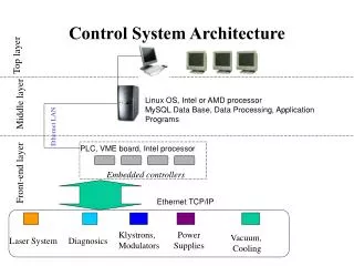
State of the Art: Airbus FCS Architecture • Initially : Mechanical
State of the Art: Airbus FCCs • System functions are divided between computers so that only 1 FCC is active at a time and the others are standby • Computers control each actuator with priority order, thus loss of a single computer does not mean loss of a function TE FLAP LE FLAP AE FLAP RUDDER ELEVTR Pilot Control FCC1 FCC2 FCC3 FCC4 FCC5
Pilot Control State of the Art: Airbus FCCs • Control and monitoring units can be thought of as two identical computers placed side by side • Comparator detects errors and performs the final action: • Same – control order is sent to actuator • Different – computer cuts connection to actuator, prevents error from propagating Control Processor Processor Memory Memory Input / Output Power Supply Power Supply Watchdog Watchdog Comparator Input / Output Monitoring
Redundancy • Multiple flight control computers • FCCs are often the only control path between the pilot and the actuators. • If FCCs fail, the pilot will not be able to control the aircraft. • Duplex flight control computers • Error checking is handled by control and monitoring units of FCCs • Result: A lot of extra hardware
Outline • Introduction • State of the Art: Airbus FCS • MassiveVotingArchitecture • Modeling and Simulation • Conclusions
Massive Voting Architecture • Enabled by “Smart” actuators • Includes processing elements implemented on ASIC or FPGA • Data processing and control functionality is distributed into subsystems making them more and more intelligent • Redundancy management is allocated to actuators • FCCs still maintain system authority • Overall critical function and control remains in the primary computers • Simplex FCCs generate commands but are not excluded if erroneous • Error checking is performed by flight control remote modules (FCRM) • Each FCRM contains 1 voter • Voters compare received commands and select the most reliable one
Pilot Control FCC1 FCC2 FCC3 FCC4 FCC5 TE FLAP LE FLAP AE FLAP RUDDER ELEVTR ADCN Network FCRM2 FCRM3 FCRM1 FCRM4 V V V V Actuator Actuator Actuator Actuator
Voting Example • Error checking is performed by FCRM FFC 1 – LE FLAP 20 FFC 2 – LE FLAP 20 FFC 3 – LE FLAP 31 FFC 4 – LE FLAP 20 FFC 5 – LE FLAP 20 FCC1 FCC1 FCC1 FCRM 4 FCRM 3 FCRM2 FCRM1 V V V Voter Actuator Actuator Actuator Actuator
Hardware Minimization • Simplex FCCs are half the size of previous FCCs • Distributed System • Previously, when an FCC produced an erroneous message, it would be marked as unreliable and all communication to the actuator would be cut • By moving error detection and logic to actuator nodes, the non-faulty parts of all computers can still contribute • Thus, fewer FCCs are required to implement a system with the same amount of reliability • Voting Algorithms • Most do not demand high processing capabilities thus hardware size is not a limitation at FCRM nodes
Outline • Introduction • State of the Art: Airbus FCS • MassiveVotingArchitecture • Modeling and Simulation • Conclusions
Modeling • Model Construction • ALTARICA – modeling language • for safety critical systems • Part 1: A textual description to • describe both functional and • dysfunctional behaviors of each • component (FCC, Voters, etc.) • Part 2: A graphical representation • to reflect the flow of information • for each state • Simulation • Test case: FCC1 sends a fault command to actuator nodes • Result: FCC1 failure has no influence in the surface control since the vote masks the faulty value and delivers the correct one. A negative acknowledgement was sent to faulty FCC.
Data Results • Aviation Safety Requirement • Failure rate for “Loss of both elevator control” must be less than 10-9 per flight hour • Results exceeded requirement!
Outline • Introduction • State of the Art: Airbus FCS • MassiveVotingArchitecture • Modeling and Simulation • Conclusions
Conclusions • Design of flight control systems is complex due to the strict requirements for aviation safety • Most flight control systems rely on a lot of redundancy to account for system failures at the cost of additional hardware • The massive voting architecture is a new way to incorporate redundancy into a flight control system while minimizing the amount of hardware required • Simulation of the massive voting architecture proved that it is just as reliable as other FCS implementations
References • http://en.wikipedia.org/wiki/Aircraft_flight_control_system • Traverse, P., I. Lacaze and J. Souyris, 2004, Airbus Fly-By-Wire: A Total Approach to Dependability, in Proceedings of the 18th IFIP World Computer Congress (WCC 2004), Building the Information Society, Kluwer Academic Publishers, Toulouse, France, August 22-27, pp. 191-212. • Brière, D. and P. Traverse, 1993, Airbus A320/A330/A340 Electrical Flight Controls – A Family of Fault-Tolerant Systems, in Proceedings of the 23rd IEEE International Symposium on Fault-TolerantComputing TCS-23), Toulouse, France, June 22-24, pp. 616-623. • Yeh, Y.C., 1996, Triple-Triple Redundant 777 Primary Flight Computer, in Proceedings of the IEEE Aerospace Applications Conference, Aspen, CO, • USA, February 3-10, pp. 293-307.