Download

1 / 15
150 likes | 241 Views
Explore the critical aspects of computer-aided design (CAD) model creation for effective coil fabrication, including alignment, tolerance propagation, and quality assurance. Discover expert tips on scripts, coordinates, and reference marks to ensure accurate fabrication stages and assembly processes.

E N D
Fabrication :- Alignment, tolerances and tolerance propagation, and quality assurance Simon’s thoughts/musings and HSX experiences Feb 05
1 Computer Design : CAD model • The coils and winding surfaces should be generated from the ORIGINAL computer model used to generate the magnetics • Feeds and busswork should be included in the model • A script file should be used to go from the computer to CAD or CAD to computer • Once generated, this is a non-changeable script ! • Generating appropriate input from CAD for a computer magnetics model is not trivial • The same coordinates used for NC machining should probably be used for checking and verification, and used in the CAD model • How many coordinate system does one use and keep track of ?
2 Scripts and coordinates • Create Scripts or Lisp files or ?? for the CAD program • A script to move the coil or object and ALL reference points to correct coordinate system for the current operation • A script to reverse this to get everything, including measurements, back to the original coordinate system • Only these tested scripts are used on a copy of the original CAD design drawing for either direction • Keep a propagation-series of this drawing at each stage annotated to show what and where and why this differs from the previous version • Scripts provide reliable and reproducible and checkable design manipulation
2 Scripts and coordinates - #2 • Without an electronic design, measurement and tolerancing from CMM become very hard and difficult to trace • Comparisons of complicated surfaces and shapes are difficult to make • Measurements are often offset by a ball diameter when using the CMM probe • A line or set of points are measured, and then compared to a CAD-generated surface. • These measurements are then later used to generate a set of surfaces or filaments for computer modeling • Immediate comparison to CAD models needs to be made to verify winding etc. • CMM measurement output conversion to computer input needs to be possible
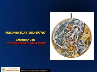
Coils from scripts Coil 4 as generated from computer model – 7 turns and 2 layers In HSX space as it will be assembled
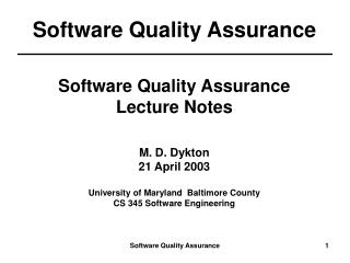
Coils from scripts #2 Coil 4 in position for winding, generated from script – plus winding surfaces Coordinate system is built into winding base, plus reference marks inserted for winding form and for fabrication
Coils from scripts #3 Final winding mold design with reference planes and winding mold components All from original coil drawing
3 Reference marks • One needs reference marks for each stage and each type of fabrication • Tooling balls for CNC mill/lathe and CMM for checking this stage • Tooling balls or detents for CMM checks during coil winding, and jigging fixtures for quick tolerance checks (David A’s go/no-go blocks) • Tooling balls or detents for CMM checks at assembly • Tooling balls or detents for finished assembly to check other components like port locations and orientations, diagnostic locations, etc.
3 Reference marks #2 • References need to be easily/sensibly accessible during each stage • A new set of measurements might be measured relative to a second or third order set of references, so errors will propagate unless original absolute reference marks are always accessible through all fabrication and assembly stages. • One really does not align a model in general, but aligns a set of reference points! Then measurements are performed relative to this alignment. So the reference points are crucial. It is difficult to have too many initial accurate reference points.
4 Tolerances • Fabrication and assembly has to have an allowable size/location for each measurable component or stage in fabrication, and an overall tolerance/allowance for a completed part • Each stage of fabrication • The winding mold • Each turn of a winding • Each layer of a winding • Cross-overs and feeds • The full coil • The full assembly
4 Tolerances - #2 • Decisions need to be made at all stages on allowable tolerances, and overall tolerances, based on computer models. One needs to set these tolerances/allowances before construction, and reassess during fabrication and assembly • The style of component and method of coil fabrication dictate the final magnet-current distribution – insulated turns, spiraled copper, keystone effects, conforming to an internal bend, cooling channels, … • Model errors and tolerances • Model As-built coils to get B Spectrum and magnetics
5 CMM Alignments • The style of alignment for a CMM to a set of reference points dictates accuracies and a possible bias in alignment • 1,2,3 alignment locates the first measured point EXACTLY on the appropriate CAD reference point, puts point #2 along the line joining the EXACT CAD 1-to-2 line, and the moves everything to get point number 3 into the 1-2-3 plane. So, my point is that #1 reference is fully accurate, but the others are not and progressively so! • Best-fit alignment does an average fit over all chosen points • how many point should one chose? • Always use the same points or number of points? • The style of alignment needs to have an error analysis done and an error propagation considered.
6 Consistency • One must consider the effect on low and high order m and n numbers of consistency in fabrication and assembly and alignment. • The same winding crew will probably use a consistent method to make a coil which might lead to a higher order error – half-period periodicity • The same winding crew will probably get better at a coil, so it might get tighter in tolerance in some dimension (flatness or radial build or tightness on a corner). If these coils are assembled in the order they are built, then most probably a low-order error is introduced • Different crews making the same coil will do it differently - with tolerances and allowances in different locations
6 Consistency #2 • A consistent alignment methodology probably influences some magnetics components more than others – modeling is necessary • Assembly by different crews will possibly lead to consistent differences, and thus non-random errors • Overall, is random better, is low-order better, is the B spectrum crucial, are surfaces crucial, or is iota crucial (coil aspect ratio affects this) ? • One needs to be able to go reliably from computer model to CAD and from CAD to computer modeling – Scripts ! • Try to model the as-built components on as low a level as possible – each coil turn? • Can the CAD model or CMM measurement generate and ascii output/excel file which can then be read into a computer file as input to generate a current model of current paths?
7 Changes • If a design changes, these have to be signed-off by both the physicists and the engineers • ATF had a huge field error from an on-the-fly engineering change splitting the main coil-feed busswork to go around a support, which was not discussed with the physics crew. • One needs to build as the CAD model dictates, generated by the computer model if appropriate (coils and feeds) • Current paths dictate I and thus B • Supports affect alignment and assembly, and therefore B • Structures and breaks affect image current and eddy current and thus B • Final as-built, or as intended to be built, components need to be reverse engineered (from scripts) into the computer model • Finite-mu modeling is difficult. What is acceptable?


![G3 - RADIO WAVE PROPAGATION [3 Exam Questions -- 3 Groups]](https://cdn3.slideserve.com/5901389/g3-radio-wave-propagation-3-exam-questions-3-groups-dt.jpg)