Download
1 / 32
320 likes | 323 Views
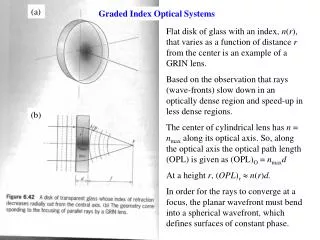
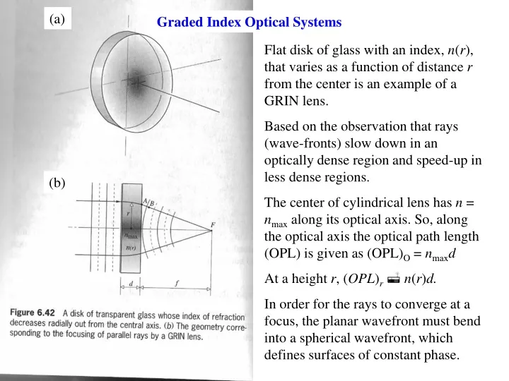
(a). Graded Index Optical Systems. Flat disk of glass with an index, n ( r ), that varies as a function of distance r from the center is an example of a GRIN lens. Based on the observation that rays (wave-fronts) slow down in an optically dense region and speed-up in less dense regions.

E N D
(a) Graded Index Optical Systems Flat disk of glass with an index, n(r), that varies as a function of distance r from the center is an example of a GRIN lens. Based on the observation that rays (wave-fronts) slow down in an optically dense region and speed-up in less dense regions. The center of cylindrical lens has n = nmax along its optical axis. So, along the optical axis the optical path length (OPL) is given as (OPL)O = nmaxd At a height r, (OPL)r n(r)d. In order for the rays to converge at a focus, the planar wavefront must bend into a spherical wavefront, which defines surfaces of constant phase. (b)
In order to match the phase at all points on the wavefront we must require nmax n(r) r Similar to a multimode-graded index core optical fiber
The most common device is a GRIN cylinder a few millimeters in diameter. They are usually fabricated using an ionic diffusion process in which a homogeneous glass is immersed in a molten salt bath for many hours. The focal length is determined by the index change n < ~0.10. The profile is usually expressed as n(r) = nmax(1 – ar2/2) Rays striking the surface in a plane of incidence that contains the optical axis travel in a sinusoidal path have spatial period T = 2/a1/2 where a = a(). It is possible to create real erect images by changing the object distance or length L of the lens. Used in a copy machine Common Applications: Laser printers, photocopiers, fax machines (i.e. devices requiring image transfer between surfaces.)
Note that the block of glass is formed so that n = n(z). The block can then be grounded and polished into the shape of a lens. The result is a reduced n for marginal rays. Radial GRIN lenses are often specified in terms of their pitch. A 1.0 pitch rod represents L = T = 2/a1/2 (full sine wave). A pitch of 0.25 has a length of quarter sine wave T/4. It is possible to use this approach to significantly reduce the effects of spherical aberration in comparison to a regular lens in (c) to the right.
Superposition of Electromagnetic (E-M) Waves Any E-M wave satisfies the wave equation: The equation is linear since any linear combination will also satisfy this equation: This is called the principle of superposition. Consider the addition of E-M waves possessing the same frequency but having different phases:
Note that we can define a phase difference, , such that = 2 - 1. The composite wave is harmonic with the same frequency, but the amplitude and phase are different. Let = -(kx + ) = 2 - 1 = (2/)(x1 - x2), where we let 1 = 2 for now. x1 and x2 are the distances from the sources of the two waves to the point of observation and is index dependent, and so = o/n . Then, we can write If 1 = 2 = const. the two E-M waves are said to be coherent.
Suppose that we have a superposition of two waves that travel a small difference in distance (x): Consider two special cases: (1) x = (n + 1/2) (out-of-phase) and (2) x = n(in-phase); n = 0, 1, 2, 3, … Destructive Interference E = 0, which is a minimum in Intensity. In both cases n = 0, 1, 2, 3… Constructive Interference E0 = 2E01, which is a maximum in Intensity.
For the more general case in which E01 E02 Case 2: Constructive interference = 2n Case 1: Partial destructive interference = 2(n + 1/2)
Fig. 7.3 Waves out-of-phase by kx radians. Fig. 7.4 The French fighter Rafale uses active cancellation to confound (frustrate) radar detection. It sends out a nearly equal signal that is out-of-phase by /2 with the radar wave that it reflects. Therefore, the reflected and emitted waves cancel in the direction of the enemy receiver.
In general, the sum of N such E-M waves is Suppose that we have N random sources (e.g. a light bulb). Then cos(i-j)t= 0 E02t =NE201 if each atom emits waves of equal E01. This result is for an incoherent source of emitters. For a coherent source, we have i = j and the sources are in-phase which gives Each atom emits waves of equal E01.
Complex Method for Phasor Additon The addition of N E-M waves becomes The complex amplitude can be expressed as a vector in the complex plane, and is known as a phasor. The resultant complex amplitude is the sum of all constituent phasors. Which can be used to calculate the resulting irradiance from the complex amplitudes of the constituent waves.
Phasor Addition Imaginary Axis E1 Real Axis Consider the sum of two E-M waves: E = E1 + E2 From the law of cosines we can easily calculate E02 and further analysis of the geometry gives tan .
In electrical engineering, these phasors can also be written with the following notation: E1=5sint E2=10sin(t+45º) E3=sin(t-15º) E4= 10sin(t+120º) E5=8sin(t+180º) Consider the addition of these five E-M waves using the phasor addition below. 50, 1045, 1-15, 10120, and 8180 Fig. 7.7 The phasor sum of E1, E2, E3, E4 and E5. The summation of two sinusoidal functions of the same frequency using phasor additon. Here E1 is taken as the reference phasor, and since E2 leads E1 (i.e. its peak occurs at an earlier location) the angle is positive. Thus is positive and the resultant E also leads to E1.
Standing Waves: Consider reflection of E-M waves of a mirror Description of standing wave: Nodes: x = 0, /2, , 3/2, 2... Anti-Nodes: x = /4, 3/4, 5/4…. Standing wave: Time-varying amplitude with sinusoidal spatial variation (see previous slide). Now, consider the addition of two E-M waves having different frequencies:
The resultant wave is a traveling wave of frequency and wave number: (traveling wave) (modulated or time varying amplitude) Note that the Irradiance is given by the following
Beats can also be observed through the superposition of E-M waves possessing different amplitudes, as well as different frequencies. The phasor method can be used to help illustrate the formation of beats.
Heterodyne Principle Heterodyning is a method for transferring a broadcast signal from its carrier to a fixed local intermediate frequency in the receiver so that most of the receiver does not have to be retuned when you change channels. The interference of any two waves will produce a beat frequency, and this technique provides for the tuning of a radio by forcing it to produce a specific beat frequency called the "intermediate frequency" or IF.
The carrier wave exhibits a high frequency The phase velocity is given by The group velocity is given by This is the rate at which the modulation envelope or energy of the wave advances or propagates. For a general dispersion = (k) and this speed is usually less than the speed of light c. Using = vk and v = c/n For normal dispersion, dn/dk > 0 and therefore vg < v.
Polarization of Light Linear Polarization: Begin by defining individual components: It is therefore possible to define any polarization orientation with a constant vector in the x-y plane for the case of linear polarization. For linear polarization, the state of polarization is often referred to as a P- state. This is the symbol for a script P.
Circular polarization: E0 The electric field vector clearly rotates clockwise while looking back at the source from the direction of propagation. The frequency of rotation is with a period of T = 2/. This is the case of “right-circularly polarized light”. It is often expressed as an R – state. This is a script R.
E0 Right circular polarization (R – state) Left circular polarization, i.e. an L– state. The electric field vector clearly rotates counter-clockwise while looking back at the source from the direction of propagation. The frequency of rotation is with a period of T = 2/. This is the case of “left-circularly polarized light”. It is often expressed as an L– state. This is a script L.
It is easy to understand that for general parameters E0x, E0y, and , we have elliptical polarization.
Actual polarizers. Irradiance is independent of the rotation angle for the conversion of natural light (unpolarized) to linear polarization. In the figure below, only the component E01cos is transmitted I() = I(0)cos2, which is known as Malus’s Law. If Iu = I (natural or unpolarized light), then I(0) = Iu <cos2>t = Iu/2.
Dichroism –selective absorption of one of two orthogonal E components. 1. Absorption of E-field in the y-direction causes e’s to flow. 2. Re-radiation of waves that cancel incident waves polarized in the y-direction. This results in transmission of waves with E-fields perpendicular to the wires (i.e., along the x-direction).
Polaroid sheet (H-Sheet), most commonly used linear polarizer. Contains a molecular analogue of the wire grid. 1. Sheet of clear polyvinyl alcohol is heated and stretched. 2. Then it is dipped in an ink solution rich in Iodine. 3. Iodine is incorporated into straight long-chain polymeric molecules allowing electron conduction along the chain, simulating a metal wire. HN-50 is the designation of a hypothetical, ideal H-sheet that transmits 50% of the incident natural light while absorbing the other 50%. In practice, about 4% of the light will be reflected at each surface leaving a maximum transmittance of 92% for linearly polarized light incident on the sheet. Thus, HN-46 would transmit 46% of incident natural light, and might be the optimal polarizer. In general, for HN-x, the irradiance of polarized light transmitted would be I=Io(x/50), where Io is the irradiance for the ideal case. In practice, it is possible to purchase HN-38, HN-32, and HN-22 in large quantities for reasonable prices, each differing in the amount of iodine present.
Tourmaline Crystal System: Hexagonal (trigonal) Habit: As well-formed, elongate, trigonal prisms, with smaller, second order prism faces on the corners. Prism faces are often striated parallel to direction of elongation (c-axis). The rounded triangular cross-sectional shape of tourmaline crystals is diagnostic; no other gem mineral has such a shape. Hardness: 7-7.5 Cleavage: none High birefringence (Two differenct indices of refraction) Strong Dichroism Any transparent gem having a mean R.I. of 1.63 and a birefringence of 0.015-0.020 is tourmaline. Tourmaline is widespread in metamorphic, igneous and sedimentary rocks. Gem Elbaite is, however, nearly restricted to pegmatites. Literally thousands of tourmaline-bearing pegmatites are known; only a few hundred apparently contain gem quality material in mineable quantities. Found in Brazil, Sri Lanka, U.S., Southern California
1) There is a specific direction within the crystal known as the principal or optic axis. 2) The E-field component of an incident wave that is perpendicular to the optic axis is strongly absorbed. 3) The thicker the crystal the more complete will be the absorption. 4) A plate cut from a tourmaline crystal parallel to its principle axis and several mm thick will serve as a linear polarizer. 5) Absorption depends on . 6) Advantages over H-sheet polarizers with regard to maximum irradiance permitted and can be used with high power lasers.