Download
1 / 10
100 likes | 213 Views
RF for CLIC DR A very first look. 16.10.2008 Alexej Grudiev. CLIC DR energy acceptance Scaling NLC DR RF system to CLIC * Traveling versus Standing wave system RF source issue Conclusions. Outline.

E N D
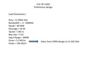
RF for CLIC DR A very first look 16.10.2008 Alexej Grudiev
CLIC DR energy acceptance Scaling NLC DR RF system to CLIC * Traveling versus Standing wave system RF source issue Conclusions Outline * Parameters of NLC DR RF are taken from “Collective effects in the NLC damping ring design” T. Raubenheimer ,et. al., PAC95
Energy acceptance * From Yannis CLIC pars WG, 2/10/07
Scaling of NLC DR RF cavity Five 1 MW CW klystrons feeding 5 SW 5-cells accelerating structures would do it. ηrf-to-beam< 30% Total length ≥2m
TW versus SW acc. structure • Several fully beam loaded travelling wave accelerating structures with shorter filling time ~20ns could increase efficiency significantly but only at fixed (nominal) current and voltage. • SW structure would require tunable coupler in order to change the loaded Q-factor and maintain efficiency when changing beam current • In summary, both systems are possible
RF power source • In case of a klystron, • It must be pulsed with DR revolution frequency of ~1 MHz repetition rate in order to maintain efficiency OR • a better option would be to do pulse compression on each turn, this will also reduce peak power requirements on klystrons at the expenses of pulse compression efficiency (~70%) though • And it must have certain bandwidth in order to be able to shorten the filling time to increase efficiency (more of an issue in TWS). • Tf~50ns => df~20MHz => df/f~1% • IOTs are better choice from the point of view efficiency and bandwidth (-> efficiency). But they have less power per tube and lower gain (two stages will be required). An R&D item at 2 GHz. • Solid state rf power amplifier showed 50% efficiency from the plug at 500 MHz (SOLEIL). BUT Efficiency and power at 2 GHz -?
Vacuum Electron Device Limitations for High-Power RF Sources Considerable part of former klystron domain claimed by IOTs Why? 0.1 1 10 100 1000 Frequency (GHz) Heinz Bohlen,Thomas Grant, CPI
Wakefields of the rf system • Loss/kick factors of NLC DR rf cavity for bunch length of 3.3 mm and aperture radius of 31 mm from the reference: • Total loss factor: kl = 1.7 V/pC • Transverse kick factor: kt = 39.4 V/pC/m • Scaling to CLIC DR rf cavity for bunch length of 3.3 mm and aperture radius of 11 mm: • Total loss factor: ~1/d: kl ~ 4.8 V/pC per cell • Transverse kick factor: ~1/d3: kt ~ 873 V/pC/m per cell • Number of cavities (cells) is also higher for CLIC: ~23 • In summary: it is ~10 times higher for longitudinal wake and ~100 times higher for transverse wake for the whole rf system • One good thing is that at 2 GHz HOM damping is more compact and could be done more efficient. Q-factor of HOM could of the order of few tens or so.
CLIC DR RF system issues • Frequency: 2 GHz • Highest peak power • High average power • Very strong beam loading transient effects: • Peak beam power of ~5 MW during 156 ns • No beam power during the other 1060 ns • Small stored energy at 2 GHz • High energy loss per turn at relatively low voltage results in big sin φs = 0.95 (any examples of operation ?) • Wakefields • Pulsed heating related problem (fatigue, …)
Recommendations • Reduce energy loss per turn • This will help anyway • Consider frequency reduction down to 1 GHz • It makes rf system a conventional high power rf system (other DRs, B-factories, etc.) • One can take advantage of a superconducting RF system • Reduce beam peak power by 2, so the SR peak power, less pulsed heating, less rf peak power, etc. • It makes life easier for positron capture • BUT • Recombination of bunches is necessary at extraction or in a separate delay loop. Potential impact on the beam emittance must be addressed.