Download
1 / 21
210 likes | 304 Views
Understand the fundamentals of memory organization and data files in MicroLogix 1000 controllers. Learn about various data types such as ASCII, integer, BCD, and more. Explore the functionalities of output, input, status, timer, counter, and control files.

E N D
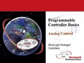
Programmable ControllerBasicsMemory & Data MicroLogix Packaged Controllers
We are going to discuss... 1. Memory 2. Data 3. Data Files
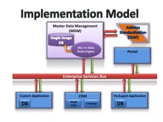
0 1 2 Output File 3 Input File 4 Status File Bit File 5 6 Timer File 7 Counter File Control File Integer Files 0 1 2 System 3 Reserved 4 5 Main Program Error File 6 - 15 HSC File STI File Subroutine Files ML 1000 Memory Organization DATA FILES MicroLogix 1000 MEMORY PROGRAM FILES MicroLogix 1000 only
DATA FILES 0 1 2 Output File Input File 3 4 Status File Bit File 5 6 Timer File 7 Counter File Control File Integer Files ML 1000 Memory Organization MicroLogix 1000 MEMORY MicroLogix 1000 only
MEMORY Bit = 1or 0 Nibble = 4 bits Byte = 2 nibbles Word(16 bits) 2 bytes Double Word= 2 words 32 bits Long Word=2 Double words 64 bits DATA Octal 0-7 BCD 0-9 HEX 0-F (15) Integer (signed) -32768 to +32767 Unsigned Integer 65,535 (32767 + 32767) Floating Point IEEE +/- 3.45x1038 to +/-1.17x10-38 Memory & Data Underlined text for MicroLogix 1000 only
7 6 5 4 15 14 13 12 11 10 9 8 3 2 1 0 0000 0000 0000 0000 Word =16 bits : 7 6 5 4 15 14 13 12 11 10 9 8 3 2 1 0 0000 0000 0000 0000 ASCII Data : Integer Data : Signed INTEGER between -32,768 & 32,767 7 6 5 4 15 14 13 12 11 10 9 8 3 2 1 0 0000 0000 0000 0000 BCD Data : 7 6 5 4 15 14 13 12 11 10 9 8 3 2 1 0 0000 0000 0000 0000 HEX Data : Data Structure
Bit Number (0-5,11) 0 Outputs File contains 6 or 12 Outputs Input Number (0-9,19) 1 Inputs File contains 10 or 20 Inputs Inputs & Outputs File #0 File Type O0:0/0 11 5 0 File Number 0 0 0 0 0 0 0 0 0 0 0 0 Word 0 File Type File #1 I1:0/0 15 0 9 File Number 0 0 0 0 0 0 0 0 0 0 0 0 0 0 0 0 Word 0 Word 1 0 0 0 0 16 19
Status File • File #2 • General purpose file that consists of 32 registers (words). These registers are mixed in “word” and “bit” formats depending on the function they represent. The Status file is primarily used for: • Setting system operating features, • Displaying system status and faults • Programming aids consisting of: • Timebase bits • Math overflow flags • Index registers • Subroutine control
7 6 5 4 15 14 13 12 11 10 9 8 3 2 1 0 7 6 5 4 15 14 13 12 11 10 9 8 3 2 1 0 0000 0000 0000 0000 Word 0: 31 30 29 28 27 26 25 24 23 22 21 20 19 18 17 16 7 6 5 4 15 14 13 12 11 10 9 8 3 2 1 0 0000 0000 0000 0000 Word 1: 47 46 45 44 43 42 41 40 39 38 37 36 35 34 33 32 7 6 5 4 15 14 13 12 11 10 9 8 3 2 1 0 0000 0000 0000 0000 Word 2: 511 496 7 6 5 4 15 14 13 12 11 10 9 8 3 2 1 0 0000 0000 0000 0000 Word 31: Bit File • File #3 (32 registers or words) B3:1/0 (RSLogix,APS) OR (HHP) B/16
I:0.0 | | 0 Timers • Timer Operation • The timer times as long as its rung is TRUE. When the timer times up to a specified value, it alerts the rest of the program by setting a bit. When the rung becomes FALSE, the timer stops timing and resets itself to zero.
File Type Timer Number (0-39) T4:0 4 Timers File Number File contains 40 timers Timers • File #4 • 40 Timers (MicroLogix 1000 only) • TON, TOF, and RTO • Timer On Delay • Timer Off Delay • Retentive Timer On • .01 and 1 second time base
File Type Timer Number (0-39) T4:0 4 Timers 15 14 13 File Number File contains 40 timers EN TT DN Word 0 Preset Value Word 1 Accumulated Value Word 2 Timers Preset T4:0.PRE How long the timer should time for. Accumulated T4:0.ACC How long the timer has timed for already. Done T4:0/DN Set to “1” when accumulated value > preset value. Timer Timing T4:0/TT Set to “1” when accumulated value < preset value. Enable T4:0/EN Set to “1” when the rung containing the timer is true.
Stop Motor Start Timer Done T4:0/DN I:0/1 O:0/3 I:0/0 ]/[ ]/[ ] [ ( ) M1 O:0/3 ] [ M1 TON O:0/3 (EN) ] [ TIMER ON DELAY Timer T4:0 Time Base 1.0 Preset 10 Accum 0 (DN) Timers • The Timer’s “done bit” turns the motor off after a 10 second time delay
I:0.0 | | 0 Counters • Counter Operation • The counter counts (by one) every time its rung goes from FALSE to TRUE. When a specified number of counts has been reached, the counter alerts the rest of the program by setting a bit. The program must reset the counter to start counting from zero again.
File Type Counter Number (0-31) C5:0 5 Counters File contains 32 counters File Number Counters • File #5 • 32 Counters (MicroLogix 1000 only) • Up, Down, Up/Down
File Type Counter Number (0-31) C5:0 5 Counters 12 11 15 14 13 Word 0 UN OV CU CD DN Preset Value Word 1 File contains 32 counters File Number Accumulated Value Word 2 Counters Preset C5:0.PRE How many the counter should count up to Accumulated C5:0.ACC How many the counter has counted already. Done C5:0/DN Set to “1” when accumulated value > preset value. Count Up C5:0/CU Set to “1” when state of CTU rung are true. Count Down C5:0/CD Set to “1” when state of CTD rung are true. Over/Underflow C5:0/OV,UN Set to “1” when counter counts past 32,767 or -32,768.
Start I:0/0 ] [ M1 O:0/3 M1 O:0/3 (RES) Counters • The Counters “done bit” stops the motor from running, after 10 operations. Stop Counter Done Motor C5:0/DN I:0/1 O:0/3 ]/[ ]/[ ( ) ] [ CTU (CU) ] [ Count Up Counter C5:0 Preset 10 Accum 0 (DN) Reset C5:0 I:0/4 ] [
Control • File #6 • Used for higher level application specific commands. • FIFO/LIFO Stacks • Sequencers • Bit Shifts etc.. • Required to allow the PLC to “manage/control” the application instruction. • 16 Registers (words) in MicroLogix 1000
File Type Control Number (0-15) R6:0 6 Control File contains 16 controls File Number Control Word 0 EN EU DN EM ER UL IN FD Error Code Word 1 Length Value Word 2 Position Value Length R6:0.LEN Length of control file Position R6:0.POS Position in control file Enable R6:0/EN Set to “1” when state of Control rung are true. Unload Enable R6:0/EU See FFU and LFU Done R6:0/DN See Instruction type Stack Empty R6:0/EM Set to “1” when stack is empty. Error R6:0/ER Set to “1” when error encountered . Unload R6:0/UL Stores status of bit unloaded (Bit shift only) Inhibit R6:0/IN See Instruction Type Found R6:0/FD SeeSequencer compare instruction (SQC)
Integer • File #7 • General purpose data registers (words) • Primarily used for: • Comparison instructions • Math instructions • Sequencers • FIFO and LIFO stacks • 105 Registers (words) in MicroLogix 1000